Watlow EZwarePlus Programming User Manual
Page 170
162
EZwarePlus Programming Manual
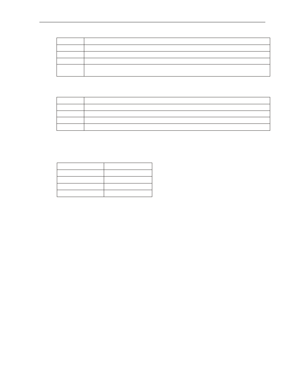
7. Set up the Target indicator. This selects the color of the filled part of the bar when it reaches a preset value.
Function
Description
Enable
When checked, the Target Indicator is active.
Color
Set the color to change the bar when the value is equal to the Target Value.
Target Value The value at which to change the color of the bar.
Tolerance
Set a tolerance for the Target Value. When the value is less than or greater than the Target Value
by this value, the bar will remain in the selected color.
8. Select the Alarm indicators colors.
Function
Description
Low Limit
The value at which the bar will change to the Low Color.
Low Color
The color to change the bar when the value reaches the Low Limit.
High Limit
The value at which the bar will change to the High Color.
High Color
The color to change the bar when the value reaches the High Limit.
9. Set up Target/alarm/zero (span) dynamic address. When checked, this option allows certain alarm limits to
be read from the PLC / Controller. The Target value, and Low limit, and High limit fields are disabled. When
Dynamic zero/span is checked, the Zero and Span fields are disabled. Data is read from the PLC as follows:
Specified Address
Low Limit
Specified Address + 1 High Limit
Specified Address + 2 Target Value
Specified Address + 3 Zero Value
Specified Address + 4 Span Value
10. Once the part is placed onto the window, you can adjust the attributes of the Bar Graph by double-clicking
on the part.
1010-1015, Rev. 03