Watlow ANAWIN 2 User Manual
Page 54
5-14 AnaWin User’s Guide
Setting Channel Parameters
Trigger (#1 and #2): You can define up to two triggers per segment.
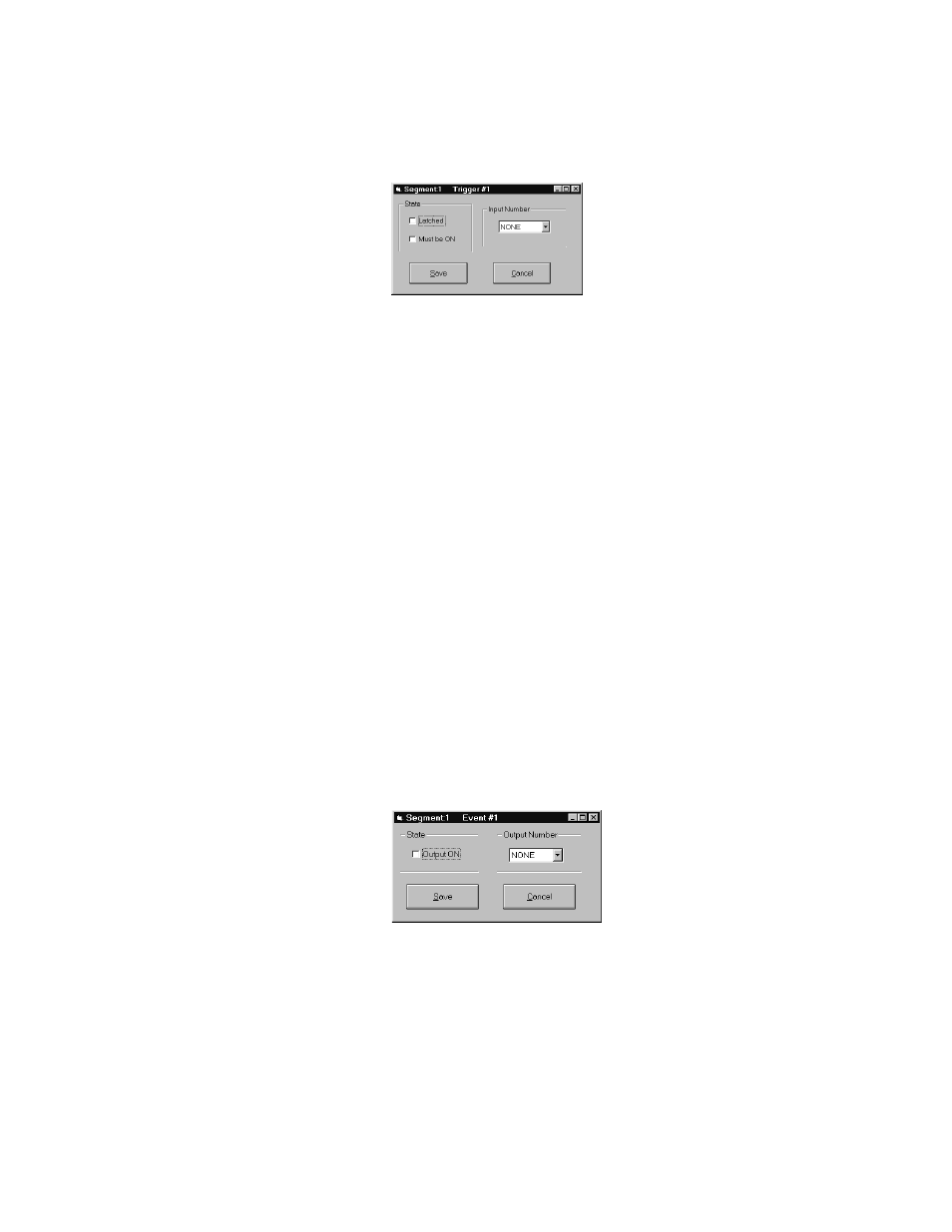
Click Trigger #1 or Trigger #2 to display the Trigger window for that
trigger. Figure 5-17 shows a sample Trigger window.
FIGURE 5-17
Trigger Window
To define a trigger, follow these steps:
1.
Use the options in the State panel to specify whether the trigger is
latched or unlatched and whether or not the trigger must be on.
•
Select Latched to define a latched trigger. Deselect Latched
to define an unlatched trigger. A latched trigger, once it
becomes active, is not checked again for the duration of the
segment. An unlatched trigger is checked continuously dur-
ing the segment.
•
Select Must be ON if you want to require a digital input to be
on. Deselect Must be ON to require a digital input to be off.
2.
Use the Input Number pull-down list box to select the input number
for which you want to set the trigger. Select NONE for no trigger
condition.
3.
Click Save to save the trigger and return to the Ramp Soak Edit
screen. A notation representing the trigger you defined now appears
in the Trigger row. For example, the notation 1-ON-U indicates a
trigger for input number 1 that is on and unlatched.
Event (#1, #2, #3, and #4): You can define up to four events per
segment. An event is a digital output. Click Event #1, Event #2, Event
#3 or Event #2 to display the Event window for that event. Figure 5-18
shows a sample Event window.
FIGURE 5-18
Event Window