0 single-phase transformer test procedure, Single-phase transformer test procedure, Table 5.0 – Vanguard Tri-Phase User Manual
Page 28
TRI-PHASE OPERATING™ INSTRUCTIONS
28
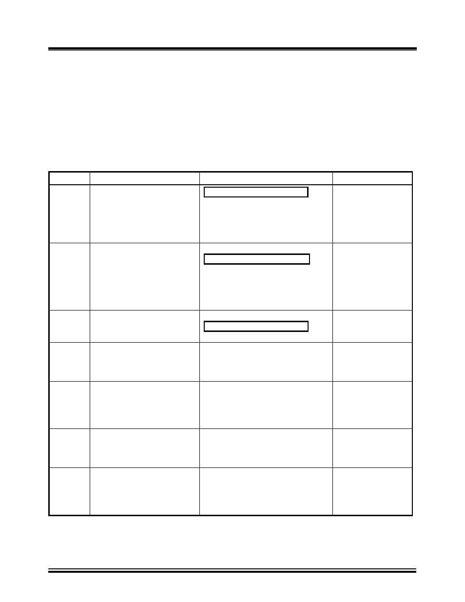
13.0 Single-Phase Transformer Test Procedure
Table 7.0 shows the procedure to test a single-phase transformer (2,400 V/240 V). Detailed
descriptions of each menu are provided in the following sub-sections. Refer to
.0 for
location of controls. The precondition for the following test procedure is that no previous single-
phase transformer test has been performed (i.e., no stored test results in non-volatile memory), and
there were no previous test records restored to non-volatile memory.
NOTE:
Pressing the “STOP” button aborts all tests and/or submenus
and returns the LCD screen display to the “Main Menu”.
Table 5.0
Single-Phase Transformer Test Procedure
STEP DESCRIPTION
DISPLAY
ACTION
1
Select “Run Test” from the
“Main Menu”
1.RUN TEST
2.SETUP
3.TEST PLAN
4.DIAGNOSTIC
TIME: 20:15:00
DATE: 07/16/08
Press key number 1
or push down Control
Knob
2
Select “Single Phase” from
“Transformer Configuration
Menu”
XFMR CONFIG:
1.SINGLE PHASE
2.Dy
3.Yd
4.Dd
5.Yy
6.Next Page
Press key number 1
or push down Control
Knob
3
“Transformer Name Plate
Voltage Status Display”
Select “YES”
XFMR NAME PLATE VLTG
1.YES
2.NO
Press key number 1
or push down Control
Knob
4
“Name Plate Voltage Status
Display”
Enter H line voltage from
transformer nameplate
NAME PLATE VOLTAGE:
H : X
0 :
Use keys 0-9 for data
entry of transformer
name plate voltage
5
“Name Plate Voltage Status
Display”
Confirm H voltage
NAME PLATE VOLTAGE:
H : X
2,400
:
Press “ENTER”
or push down Control
Knob
(2400 was keyed for
this test)
6
“Name Plate Voltage Status
Display”
Enter X line voltage from
transformer nameplate
NAME PLATE VOLTAGE:
H : X
2,400: 0
Use key numbers 0-9
for data entry
7
“Name Plate Voltage Status
Display”
Confirm X voltage
NAME PLATE VOLTAGE:
H : X
2,400 : 240
Press “ENTER”
or push down Control
Knob
(240 was keyed for
this test)