Vanguard Tri-Phase User Manual
Page 141
TRI-PHASE OPERATING™ INSTRUCTIONS
APPENDIX A
TRANSFORMER VECTOR GROUP CODES
Utility power transformers manufactured in accordance with IEC specifications have a Rating Plate
attached in a visible location which contains a list of the transformer's configuration and operating
specifications. One such rating is the winding configuration and phase-displacement code. This code follows
a convention that comprises letter and number sets that denote three-phase winding configurations (i.e.,
Wye, delta, or zig-zag). Letter symbols for the different windings are noted in descending order of their
rated voltages. That is, symbols denoting higher voltage ratings will be upper-case (i.e., capital) letters and
symbols denoting lower or intermediate voltage ratings will be lower-case letters. If the neutral point of
either a wye or zig-zag winding is brought out, the indication shall be an N (high voltage) or n (lower
voltage). The end numeral is a 30
° multiplier that indicates phase lag between windings.
Accordingly, the following standard practice applies:
Wye (or star) = Y (high voltage) or y (low voltage)
Delta = D (high voltage) or d (low voltage)
Zig-zag = Z (high voltage) or z (low voltage)
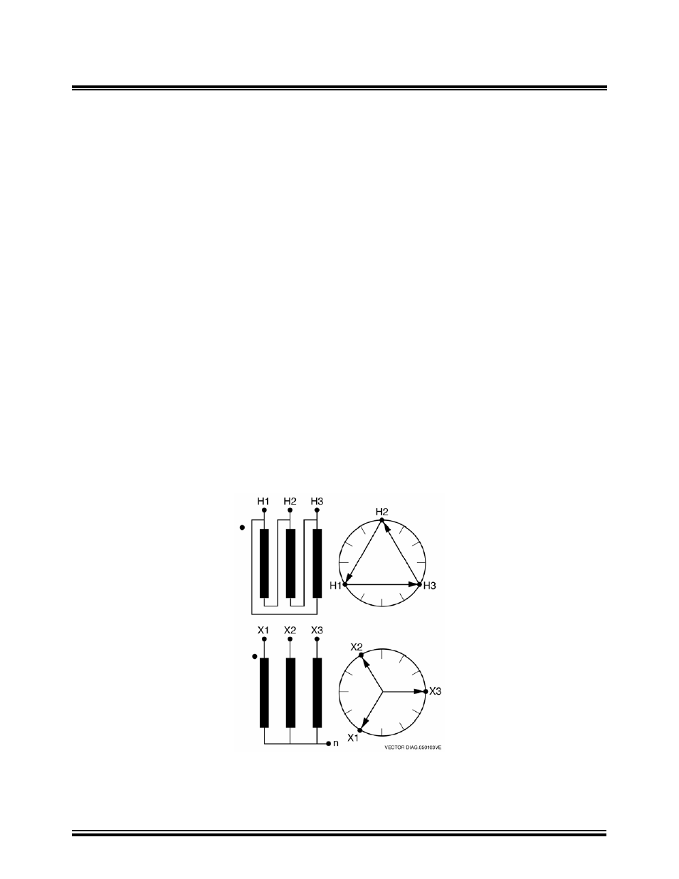
An example:
Dyn11
which decodes as follows:
D indicates that the high-voltage windings are connected in a Delta configuration
(Since delta windings do not have a neutral point, the N never appears after a D).
y indicates that the lower voltage winding is in a wye (or star) configuration.
n indicates that the lower voltage windings have the neutral point brought out.
11 indicates a phase-displacement lag of 330 degrees between the Wye and the Delta winding.
141