0 tri-phase( verification test procedure, 0 tri-phase, Verification test procedure – Vanguard Tri-Phase User Manual
Page 119: Table 23.0, Tri-phase™ verification test procedure
TRI-PHASE OPERATING™ INSTRUCTIONS
119
23.0 TRI-PHASE
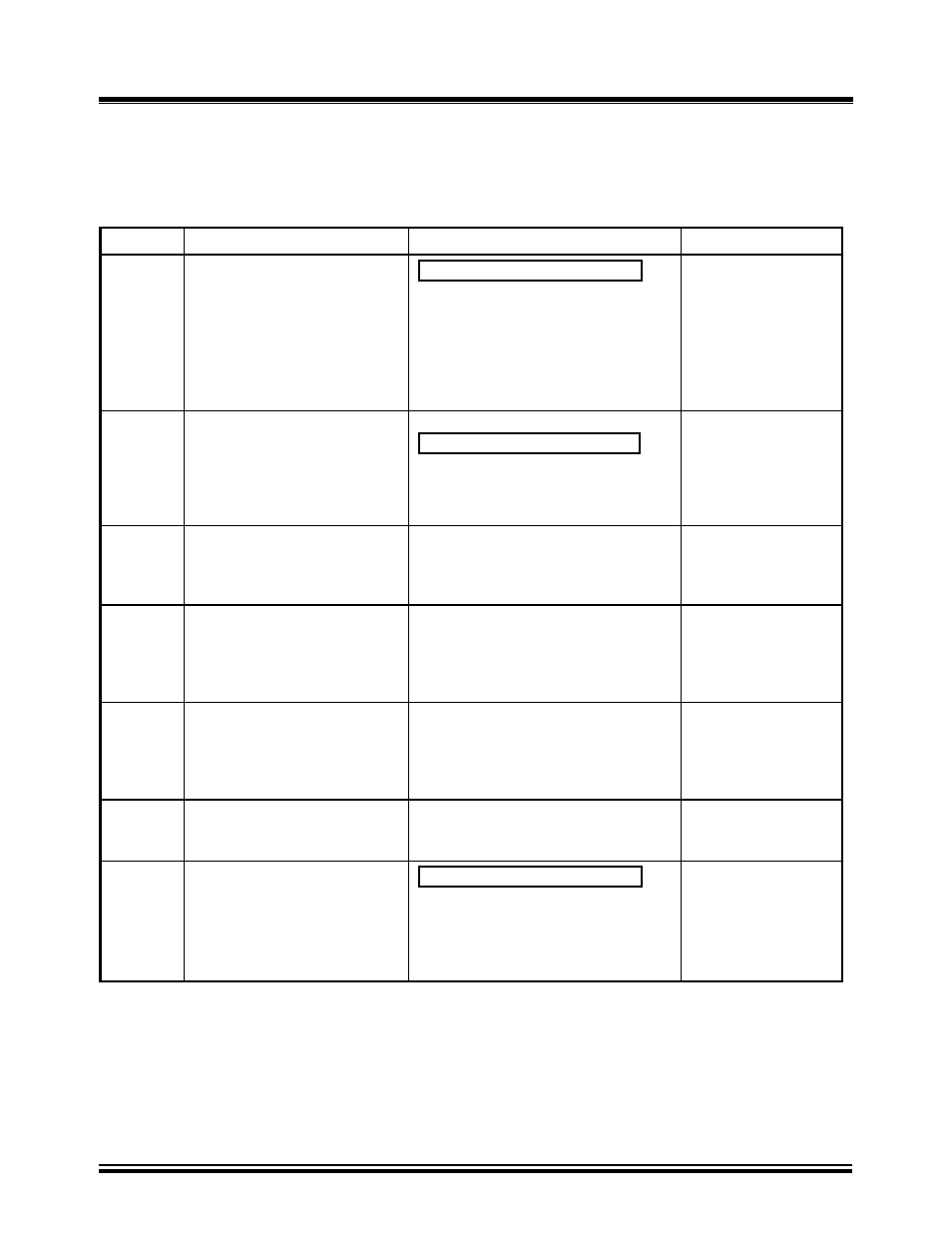
™ Verification Test Procedure
The following procedure allows the operator to perform a verification test on the TRI-PHASE™
electronics.
Table 23.0
TRI-PHASE™ Verification Test Procedure
STEP DESCRIPTION
DISPLAY
ACTION
1
Select “Diagnostic” from the
“Main Menu”
1.RUN TEST
.
2.SETUP
3.TEST PLAN
4.DIAGNOSTIC
TIME: 20:15:00
DATE: 07/16/08
Press key number 4
Selection of 4 may be
made by turning the
Control Knob. Push
down Control Knob
after 4 is selected
2
Select “Verification Test” from
the “Diagnostic Menu”
DIAGNOSTIC
1.CABLE TEST
.
2.VERIFICATION TEST
Press key number 2
Selection of 2 may be
made by turning the
Control Knob. Push
down Control Knob
after 2 is selected
3
Connect cables as instructed in
display
VERIFICATION TEST
CONNECT: H0-X0,
H1-X1
H2-X2,
H3-X3
“ENTER” TO CONTINUE
Press “ENTER” key
after connecting
cables
4
Test is performed on Delta to
Delta transformer configuration
TEST RESULTS
RATIO
mA
%DIFF
+1.0000
0001
+1.0000
0001
+1.0000
0001
Press “ENTER” key to
advance
5
Test is performed on Y to Y
transformer configuration
TEST RESULTS
RATIO
mA
%DIFF
+1.0000
0001
+1.0000
0001
+1.0000
0001
Press “ENTER” key to
advance
6
Return to “Main Menu”
TEST COMPLETE
Press any key to or
push down Control
Knob
“Main
Menu”
1.RUN TEST
.
2.SETUP
3.TEST PLAN
4.DIAGNOSTIC
TIME: 20:15:00
DATE: 07/16/08
None
NOTE:
A ratio reading of 1.0000 ±0.1% is expected for all the test combinations for the TRI-PHASE™.
Disregard the excitation current reading in this test.