14 typical three phase dyn1 test plan printout, Figure 68.0, Typical three phase dyn1 test plan printout – Vanguard Tri-Phase User Manual
Page 104
TRI-PHASE OPERATING™ INSTRUCTIONS
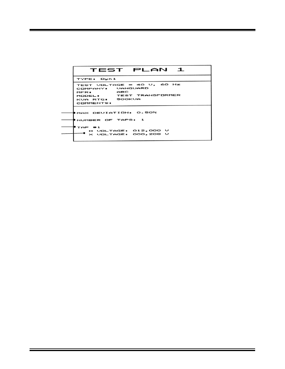
17.14 Typical Three Phase Dyn1 Test Plan Printout
The test plan test parameters are displayed in
1
2
3
4
Figure 68.0
Typical Three Phase Dyn1 Test Plan Printout
The test plan direct printout is explained below.
1. Maximum
%Diff
limit
2.
Number of tests (i.e., TAPS)
3.
Test number 1 heading
4.
Test number 1 parameters: H and X voltages
104
See also other documents in the category Vanguard Accessories for electrical:
- Resistor Transducer Adapter 9095-UC (7 pages)
- Accu-Ohm 200 S2 (4 pages)
- Accu-Trans (28 pages)
- ATO-400 (43 pages)
- ATO-400P (44 pages)
- Auto-Ohm (22 pages)
- Auto-Ohm 100_200 s2 (31 pages)
- Auto‐Ohm 200 S3 (66 pages)
- DMOM-100 (35 pages)
- DMOM-100_200 s2 (42 pages)
- DMOM-200 (33 pages)
- Herculito (17 pages)
- ATRT-01 S2 (59 pages)
- ATRT-01_01B S3 (88 pages)
- ATRT-01_01B_01D (31 pages)
- ATRT-03_03A (114 pages)
- ATRT-03_03A S2 (147 pages)
- CVT-765 (46 pages)
- CBCT (14 pages)
- CBPS-300 (16 pages)
- CT-3500 (24 pages)
- CT-3500 S2 (53 pages)
- CT-6500 (69 pages)
- CT-6500 S2 (82 pages)
- CT-7000 (83 pages)
- CT-7000 S2 (108 pages)
- CT-7000 S3 (137 pages)
- CT-7500 (76 pages)
- CT-7500 S2 (110 pages)
- CT-8000 (120 pages)
- CT-8000 S3 (145 pages)
- DigiTMR (86 pages)
- DigiTMR S2 (123 pages)
- DigiTMR S2 PC (31 pages)
- MCCB-250 (17 pages)
- UPS S2 (13 pages)
- EZCT-2000 (68 pages)
- EZCT-2000 (45 pages)
- EZCT-2000A (103 pages)
- EZCT-2000B (118 pages)
- EZCT-2000C Plus (119 pages)
- EZCT-S2 (66 pages)
- EZCT-S2A (98 pages)
- IRM-5000P (58 pages)