IAI America ERC User Manual
Page 93
73
The relationships of movement command inputs/position complete outputs and corresponding position numbers
are shown below.
For easier identification, each input/output signal has a name similar to the naming convention used with air
cylinders.
However, note that the target position is determined by the value set in the [Target position] field under each
position number. Therefore, changing the magnitude correlation of the settings in Nos. 0 to 2 will change the
meanings of the corresponding input/output signals.
Accordingly, the settings in the respective position numbers should match the semantic meanings of the
corresponding signal names used in this operation manual, unless doing so will pose a problem.
Input signal
Output signal Target
position
Rear end move (ST0)
Rear end complete (PE0)
Setting in the [Target position] field under
position No. 0 Example: 5 mm
Front end move (ST1)
Front end complete (PE1)
Setting in the [Target position] field under
position No. 1 Example: 390 mm
Intermediate point move (ST2) Intermediate point complete (PE2)
Setting in the [Target position] field under
position No. 2 Example: 200 mm
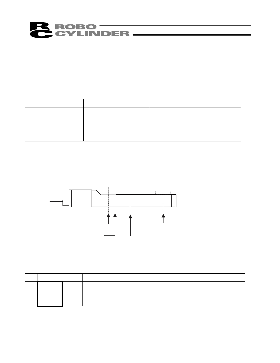
Positioning relationships on the Robo Cylinder
This example assumes the use of a slider type actuator with a 400 mm stroke.
[Motor side]
[Counter-motor side]
Position table (Field(s) within thick line must be entered.)
No. Position Speed Acceleration/deceleration
Push
Positioning band Acceleration only MAX
0 5 500
0.3
0
0.1
0
1 390 500
0.3
0
0.1
0
2 200 500
0.3
0
0.1
0
Home (0 mm)
Rear end complete (5 mm)
Front end complete (390 mm)
Intermediate point complete (200 mm)