IAI America ERC User Manual
Page 55
35
CN1
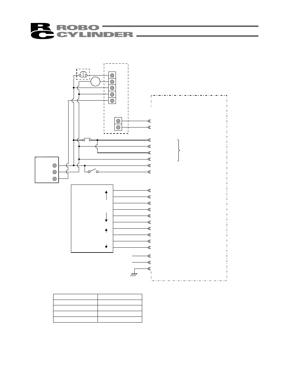
[2] When the control board is of the PNP specification [source type]
* In the case of a robot cable, the wire colors change as follows.
Wire color
Pin number
Gray (Red 1)
2A
Gray (Black 1)
2B
Gray (Red 2)
7A
Gray (Black 2)
7B
(Note) To release the brake, connect a switch between BKR and 24 V and turn on the switch.
MC
EMG2
EMG1
24V
0V
FG
TB2
60 mA
MAX
A
B
Orange (Red 1)
Orange (Black 1)
1A SGA
1B SGB
Yellow (Red 1)
Yellow (Black 1)
Pink (Red 1)
Pink (Black 1)
White (Red 1)
White (Black 1)
4A MPI
4B GND
5A MPI
5B GND
3A 24V
3B BKR
24V
0V
FG
Orange (Red 2)
Orange (Black 2)
*Light blue (Red 2)
*Light blue (Black 2)
White (Red 2)
White (Black 2)
Yellow (Red 2)
Yellow (Black 2)
Pink (Red 2)
Pink (Black 2)
6A
6B
7A
7B
8A
8B
9A
9B
10A
10B
*Light blue (Red 1)
*Light blue (Black 1)
2A EMS1
2B EMS2
FG
MC
Input power supply
Host system
Outpu
t
side
Inpu
t
side
EMG signal
Contact output for EMG switch on
teaching pendant
SIO converter (RCB-TU-SIO-A/B)
ERC actuator
Serial communication
Motor drive power supply
Control power supply
Drain wire
TB1
(Not used)
I/O interface
(Refer to the I/O connections for
each PIO pattern)
Brake release
switch
(Note)
Relay