Connection diagram – IAI America ERC User Manual
Page 57
37
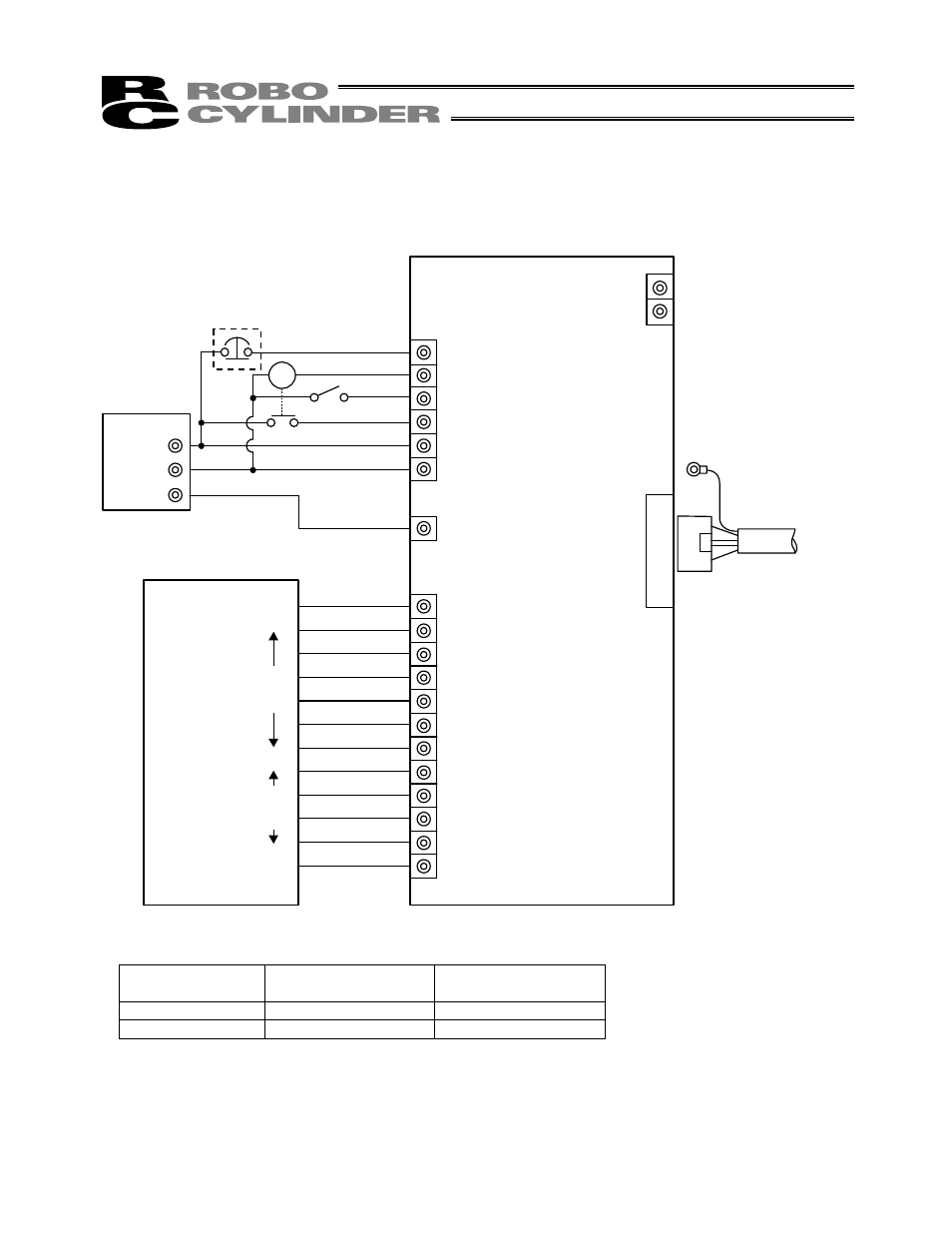
Connection
diagram
[1] When the control board is of the NPN specification [sink type]
[1] Insulate the power
supply
[2] Change to PNP
Input common
24 V
0 V
Output common
0 V
24 V
(Note) To release the brake, connect a switch between the TB1-BK terminal and 0 V and turn on the switch.
MC
24V
0V
FG
TB2
A
B
TB1
EMS2
EMS1
BK
MP
24V
0V
FG
TB4
TB3
1
2
3
4
5
6
7
8
9
10
11
12
Output
common
Input
common
EMG signal
Insulated PIO terminal block (RCB-TU-PIO-A/B)
Connect to FG
Relay cable
Input power supply
Host system
Contact output for EMG switch
on teaching pendant
Motor drive power supply
Control power supply
J1
(Not used)
Outpu
t
side
Inpu
t
side
60 mA Max
I/O interface
(Refer to 4.4, “Insulated PIO
Terminal Block.”)
Brake release
switch
(Note)
Relay
- ERC2 (138 pages)
- ERC2 (188 pages)
- ERC3 (438 pages)
- RCA-E (53 pages)
- RCA-P (42 pages)
- RCB-101-MW (38 pages)
- RCP2-C (178 pages)
- RCS-E (102 pages)
- RCA-A4R (72 pages)
- RCA-RA3C (114 pages)
- RCA-SRA4R (56 pages)
- RCA2-RA2AC (100 pages)
- RCA2-SA2AC (92 pages)
- RCA2-TA4C (134 pages)
- RCD-RA1D (40 pages)
- RCP2-BA6 (72 pages)
- RCP2-GRSS (130 pages)
- RCP2-HS8C (126 pages)
- RCP2-RA2C (120 pages)
- RCP2-RTBS (80 pages)
- RCP2W-SA16C (46 pages)
- RCP3-RA2AC (60 pages)
- RCP4-RA5C (82 pages)
- RCP4-SA5C (94 pages)
- RCP4W (96 pages)
- RCS2-F5D (142 pages)
- RCS2-GR8 (46 pages)
- RCS2-RN5N (80 pages)
- RCS2-RT6 (60 pages)
- RCS2-SA4C (258 pages)
- RCS2-TCA5N (62 pages)
- RCL-SA1L (66 pages)
- RCL-RA1L (56 pages)
- RCLE-GR5L (46 pages)
- IK Series (16 pages)
- FS (84 pages)
- IF (76 pages)
- ISB (114 pages)
- ISDA (126 pages)
- ISDB (116 pages)
- ISPWA (90 pages)
- NS (78 pages)
- ICS(P)A (16 pages)
- RS (46 pages)