IAI America ERC User Manual
Page 65
45
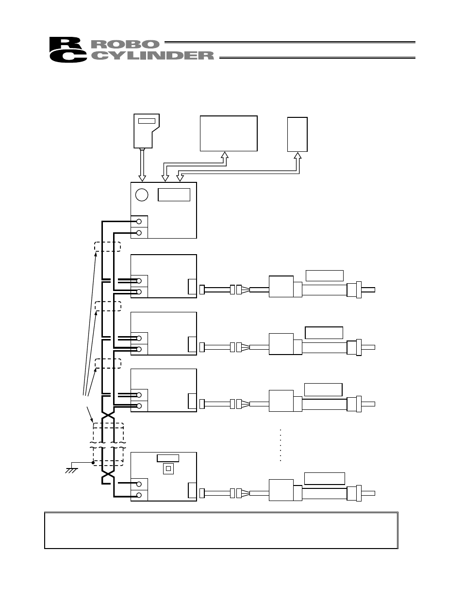
Using both SIO converter and insulated PIO terminal block
(Communication with the PLC is performed via parallel I/O connection.)
(Note 1)
Only on the last axis set the terminal-resistor connection switch to the [RTON] side.
(Note 2)
If the actuators use different power supplies, align 0 [V] on all power supplies.
(Note 3)
Connect the shielded wire of each axis to FG.
(Note 4)
If the overall length of link cable exceeds 30 m, use wire of 22AWG or larger size.
TB1
A
B
TB2
A
B
TB2
A
B
TB2
A
B
TB2
A
B
J1
J1
J1
J1
RTON
FG
SIO converter
Actuator 1
Actuator 2
Actuator 3
Actuator 16
One-pair
shielded cable
Insulated PIO terminal block
Teaching pendant
PC
PLC’s communication module
See also other documents in the category IAI America Hardware:
- ERC2 (138 pages)
- ERC2 (188 pages)
- ERC3 (438 pages)
- RCA-E (53 pages)
- RCA-P (42 pages)
- RCB-101-MW (38 pages)
- RCP2-C (178 pages)
- RCS-E (102 pages)
- RCA-A4R (72 pages)
- RCA-RA3C (114 pages)
- RCA-SRA4R (56 pages)
- RCA2-RA2AC (100 pages)
- RCA2-SA2AC (92 pages)
- RCA2-TA4C (134 pages)
- RCD-RA1D (40 pages)
- RCP2-BA6 (72 pages)
- RCP2-GRSS (130 pages)
- RCP2-HS8C (126 pages)
- RCP2-RA2C (120 pages)
- RCP2-RTBS (80 pages)
- RCP2W-SA16C (46 pages)
- RCP3-RA2AC (60 pages)
- RCP4-RA5C (82 pages)
- RCP4-SA5C (94 pages)
- RCP4W (96 pages)
- RCS2-F5D (142 pages)
- RCS2-GR8 (46 pages)
- RCS2-RN5N (80 pages)
- RCS2-RT6 (60 pages)
- RCS2-SA4C (258 pages)
- RCS2-TCA5N (62 pages)
- RCL-SA1L (66 pages)
- RCL-RA1L (56 pages)
- RCLE-GR5L (46 pages)
- IK Series (16 pages)
- FS (84 pages)
- IF (76 pages)
- ISB (114 pages)
- ISDA (126 pages)
- ISDB (116 pages)
- ISPWA (90 pages)
- NS (78 pages)
- ICS(P)A (16 pages)
- RS (46 pages)