3 parameter settings – IAI America ERC User Manual
Page 123
103
8.3 Parameter
Settings
If a parameter has been changed, always restart the controller using a software reset command or by
reconnecting the power.
8.3.1 Parameters Relating to the Actuator Stroke Range
Soft limit
Set the soft limit in the positive direction in parameter No. 3, and that in the negative direction in parameter No. 4.
The factory setting for the soft limits conforms to the effective actuator length. Change the settings, as necessary,
to prevent crash with an obstacle or when the actuator must be stroked slightly beyond its effective length.
A wrong soft limit setting will cause the actuator to crash into the mechanical end, so exercise due caution.
The minimum setting unit is “0.01 [mm].”
(Note) To change a soft limit, set a value corresponding to 0.3 mm outside of the effective range.
Example)
Set the effective range to between 0 mm and 80 mm
Parameter No. 3 (positive side) 80.3
Parameter No. 4 (negative side) –0.3
Zone boundary
Set the zone in which a zone output signal (ZONE) will turn ON.
The zone signal turns ON only when the current coordinate position is inside the negative (-) boundary and
positive (+) boundary settings.
The positive and negative boundaries for the ZONE signal are set in parameter No. 1 and No. 2, respectively.
The minimum setting unit is “0.01 [mm].”
Example) Use the zone output signal as an intermediate limit switch in the range of 100 to 200 mm, with an
actuator having a 300-mm stroke
Parameter No. 1 (positive side) 200, parameter No. 2 (negative side) 100
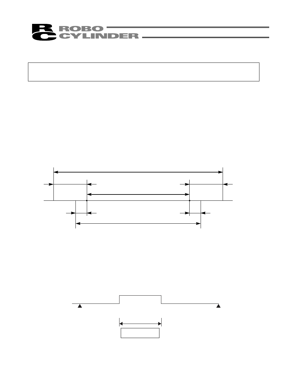
Soft limits set in the controller
Approx.
0.3 mm
Effective range
Allowable jogging/inching range after home return
Approx. 0.1 mm
Approx. 0.1 mm
Approx.
0.3 mm
8 0
0
0
(Home)
ZONE turns ON
100
200
300 mm