IAI America ERC User Manual
Page 83
63
(5) Push (Push)
Select the positioning mode or push & hold mode.
The default value is “0.”
0: Positioning mode (= Normal operation)
Other than 0: Push & hold mode [%]
To select the push & hold mode, enter the current-limiting value for the servo
motor during push & hold operation. Enter an appropriate value up to 70% in
accordance with the actuator type.
Be sure to refer to 5.1.1, “Relationship of Push Force at Standstill and Current-Limiting Value” that specifies
the relationship of the push force to be applied to the load at standstill [kgf] on one hand, and the current-
limiting value on the other, for each actuator type.
Note: If the push force is too small, a false detection of push & hold condition may occur due to slide
resistance, etc., so exercise caution.
(6) Positioning band
(Pos. band)
The function of the positioning band varies depending on whether the push &
hold setting in (5) is “0” or “other than 0.”
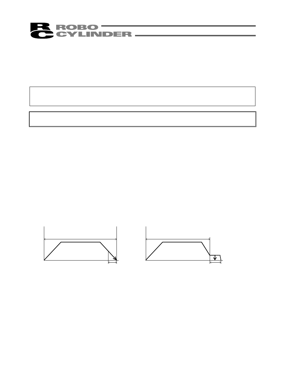
(A) Push = 0 (Positioning mode)
In the positioning mode, enter the position-complete detection width
(distance to the target position), in [mm].
The distance to the target position indicates the range prior to the target
position, upon entry of the actuator in which range a position complete signal
will be output.
The default value is “0.1 [mm]” (Fig. A).
(B) Push = Other than 0 (Push & hold mode)
Enter the maximum push amount (distance from the target) in the push &
hold mode, in [mm] (Fig. B).
If the push direction corresponds to the negative direction along the
displayed coordinate axis, add a – (minus) sign to the entered value.
Fig. A
Fig. B
Speed
Speed
(5) Push = 0
Distance to the position set in (2)
(5) Push = Other than 0
Distance to the position set in (2)
Moving distance
Moving distance
(6) Positioning band
(6) Positioning band