3 sio converter (optional) – IAI America ERC User Manual
Page 73
53
4.3 SIO Converter (Optional)
Model: RCB-TU-SIO-A (Vertical installation)
RCB-TU-SIO-B (Horizontal installation)
This unit is required if any of the following conditions applies:
[1] The actuator’s rear cover cannot be reached and therefore the teaching pendant or PC cannot be
connected.
[2] Want to execute movement operation or parameter edit for all axes when multiple axes are connected to
the single equipment.
[3] Want to operate the actuator via serial communication using the PLC’s communication module.
Explanation of functions
[1] Power/emergency-stop terminal block (TB2)
Provide a contact output for the emergency-stop switch on the teaching pendant (RCA-T/E).
EMG1 and EMG2 connect to the emergency-stop switch on the teaching pendant when the
PORT switch is ON, or are shorted when the PORT switch is OFF.
These terminals comprise an interlock with a safety circuit provided by the user.
Positive side of the 24-V power supply
Power supply for the teaching pendant and conversion circuit
Current consumption: 0.1 A max.
Negative side of the 24-V power supply
EMG1,
EMG2
24V
0V
FG
FG of the 24-V power supply
[2] Link-connection terminal block (TB1)
A connection port for linking the controller.
“A” on the left side connects to SGA (wire color: orange/red 1) in the relay cable or “A” on the insulated PIO
terminal block TB2.
“B” on the right side connects to SGB (wire color: orange/black 1) in the relay cable or “B” on the insulated
PIO terminal block TB2.
(Note) Be sure to use twisted pair wires for the above two lines (SGA/SGB).
[3] D-sub, 9-pin connector
A connection port with the host PC or PLC’s communication module.
[4] Mini DIN, 8-pin connector
A connection port with the teaching pendant.
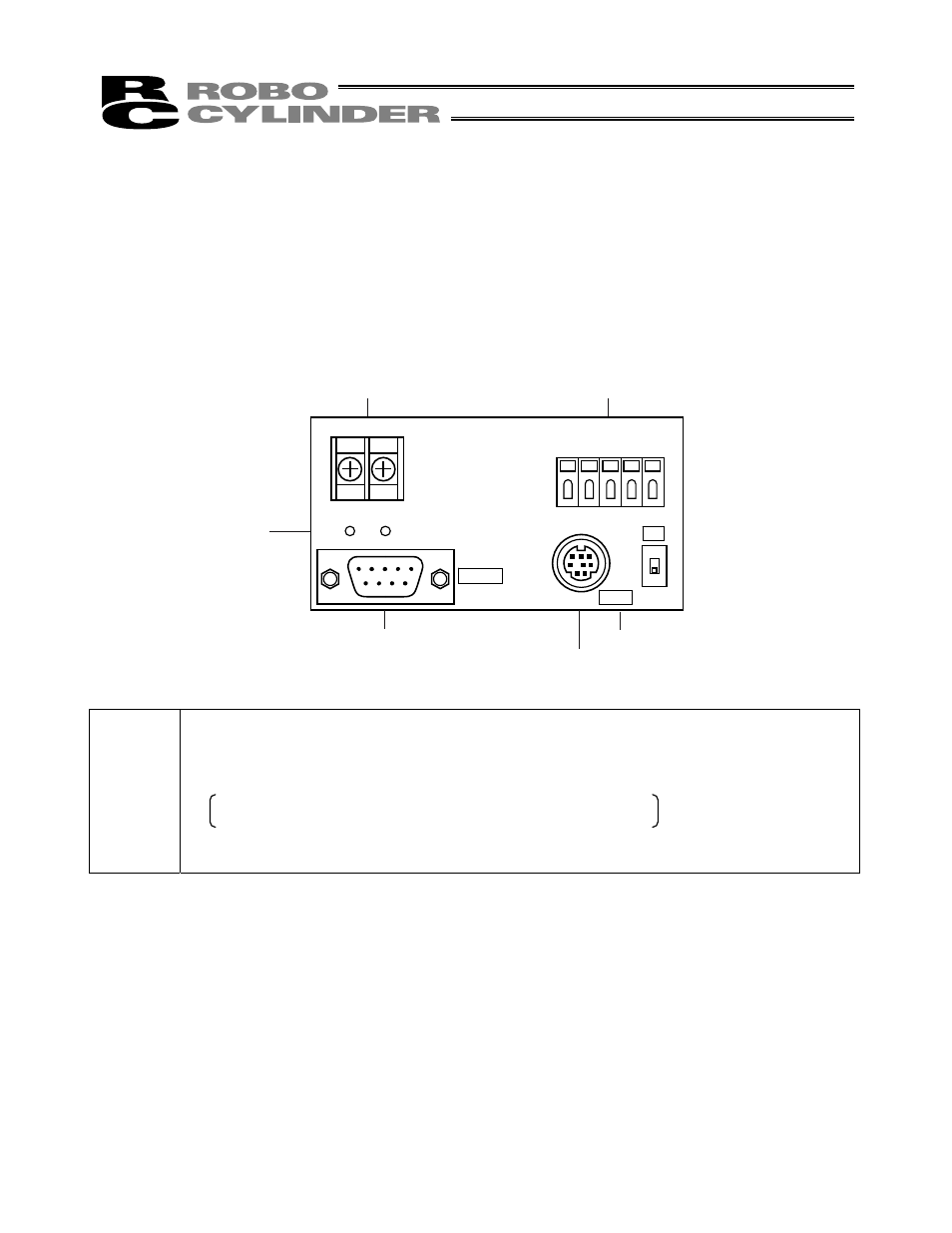
TB1
A B
TB2
EMG2
EMG1
24V
0V
FG
LED1 LED2
RS232
PORT
ON
SW1
[2] Link-connection
terminal block (TB1)
[1] Power/emergency-stop
terminal block (TB2)
[6] Monitor
LEDs
[3] D-sub, 9-pin connector
[5] PORT
switch
[4] Mini DIN, 8-pin connector