1 explanation of i/o signals, 2 details of input signals – IAI America ERC User Manual
Page 50
30
3.4.1 Explanation of I/O Signals
The following explains the signals used in the “8 points” and “16 points” patterns.
Category
Signal name
Signal
abbreviation
Function overview
Start
CSTR
Movement of the actuator starts at the rise edge of this signal.
Command
position number
PC1
PC2
PC4
PC8
This signal is used to input a position number that specifies movement.
Be sure to set a command position number by 6 ms before the start signal
(CSTR) is turned ON.
*Pause
*STP
ON: The actuator can be moved, OFF: The actuator decelerates to a stop
Input
Home return
HOME
Home return starts at the rise edge of this signal.
Position complete
PEND
This signal turns ON when the actuator has moved close enough to the target
position and entered the in-position band.
Used to determine if positioning has completed.
Home return
completion
HEND
This signal turns OFF when the power is input, and turns ON when home
return completes.
Zone ZONE
This signal is output if the current actuator position is within the range set by
the parameter upon completion of home return.
Used as a limit switch for an intermediate point or a simple ruler for push &
hold operation.
Output
*Alarm *ALM
This signal remains ON while the controller is operating properly, and turns
OFF when an alarm generates. The *ALM signal is synchronized with the
green/red indication of the LED.
(Note) The signal remains ON while the motor drive power is cut off.
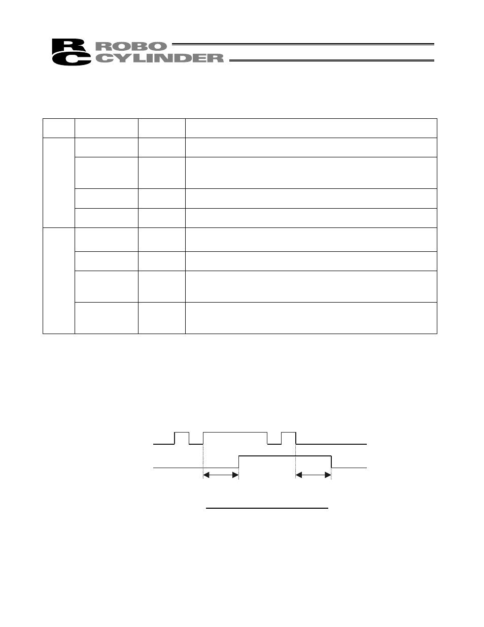
3.4.2 Details of Input Signals
The input signals from this controller have an input time constant, in order to prevent malfunction caused by
chattering, noise, etc.
Each input signal will switch the applicable setting when received continuously for 6 msec or more.
In other words, when a given input is switched from OFF to ON, the controller will recognize the ON state of the
signal only after elapse of 6 msec.
The same applies to the switching of an input from ON to OFF. (Fig. 1)
Fig. 1 Recognition of Input Signal
Start (CSTR)
When the OFF
ON rise edge of this signal is detected, the controller will read the target point number as the
3-bit binary code consisting of signals PC1 to PC4 (or 4-bit code consisting of signals PC1 to PC8 if the “16
points” pattern is selected), and perform positioning to the target position specified by the corresponding position
data.
6 [msec]
6 [msec]
Input signal
Recognition by the controller
Not recognized
Not recognized