Button icons, Front panel operations, Front panel security lockouts – Extron Electronics MVX Plus 128 VGA A User Guide User Manual
Page 34: Power, Button.icons, Front.panel.security.lockouts, Preliminar y, Operation, cont’d
Operation, cont’d
MVX Plus 128 VGA A Matrix Switcher • Operation
3-8
PRELIMINAR
Y
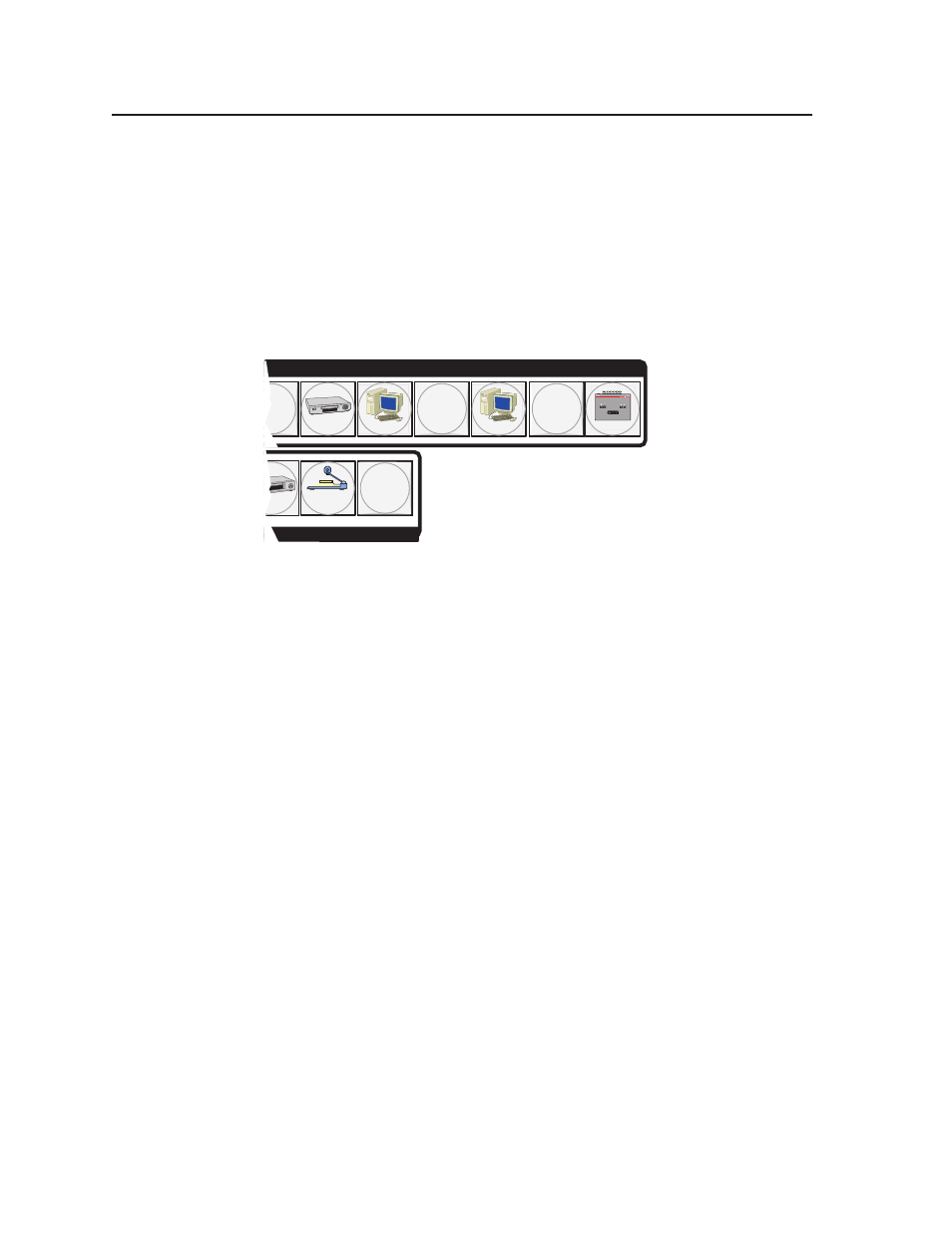
Button icons
The numbered translucent covers on the input and output pushbuttons can be
removed and replaced to insert labels behind the covers.
Input and output labels can be created easily with Extron’s Button-Label Generator
software, which ships with every Extron matrix switcher. Each input and output
can be labeled with names, alphanumeric characters, or even color bitmaps
for easy and intuitive input and output selection (figure 3-2). See chapter 5,
“Matrix Software”, for details on using the labeling software. See Appendix B,
“Specifications, Part Numbers, and Accessories”, for blank labels and a procedure
for removing and replacing the translucent covers.
DVD
VCR
Computer
Computer
Document
Camera
VTG 200
6
9
11
8
INPUTS
Figure 3-2 — Sample button icons
Front Panel Operations
The following paragraphs detail the power-up process and then provide sample
procedures for creating ties, changing a configuration, viewing configurations,
saving and recalling a preset, muting and unmuting outputs, viewing and adjusting
the audio level, viewing and adjusting the output volume, locking out the front
panel, performing one of several resets, toggling background illumination on and
off, and reading and setting the RS-232/RS-422 Remote port settings.
Front panel security lockouts
In the procedural descriptions that follow, it is assumed that the switcher is in Lock
mode 0 (fully unlocked). The following two Lock modes are also available:
• Lock mode 1 — All changes are locked from the front panel. Some functions
can be viewed.
• Lock mode 2 — Advanced features are locked and can be viewed only. Basic
functions are unlocked.
N
The switcher is shipped from the factory in
Lock mode 2.
See “Setting the front panel locks (Executive modes)” on page 3-41 for a detailed list
of basic and advanced functions and the procedure to set the various front panel
locks.
Power
Apply power by connecting the power cord to an AC source. The switcher
performs a self-test that flashes the front panel button indicators red, green, and
amber and then turns them off. An error-free power up self-test sequence leaves
all I/O and control buttons either unlit or showing background illumination. The
lit/unlit status RGBHV or Video button and the Audio button is the same as when
the switcher was powered off.