Marker delaytests – Tektronix AWG610 User Manual
Page 421
Appendix B: Performance Verification
AWG610 Arbitrary Waveform Generator User Manual
B-61
Marker DelayTests
These procedures check the marker delay function of the AWG610 Arbitrary
Waveform Generator.
Equipment
required
Two 50ĂW SMA coaxial cables, twoĂSMA(Fe)ĆBNC(Ma) adapters, two
Ă50ĂW SMA terminatorsĂ andan oscilloscope.
Prerequisites
The AWG610 Arbitrary Waveform Generator must meet the
prerequisites listedon page B-8.
NOTE. Connect two 50 W SMA terminators to the each inverted marker out-
put connectors, during the marker output tests.
NOTE. Two 50 W SMA coaxial cables must have same length.
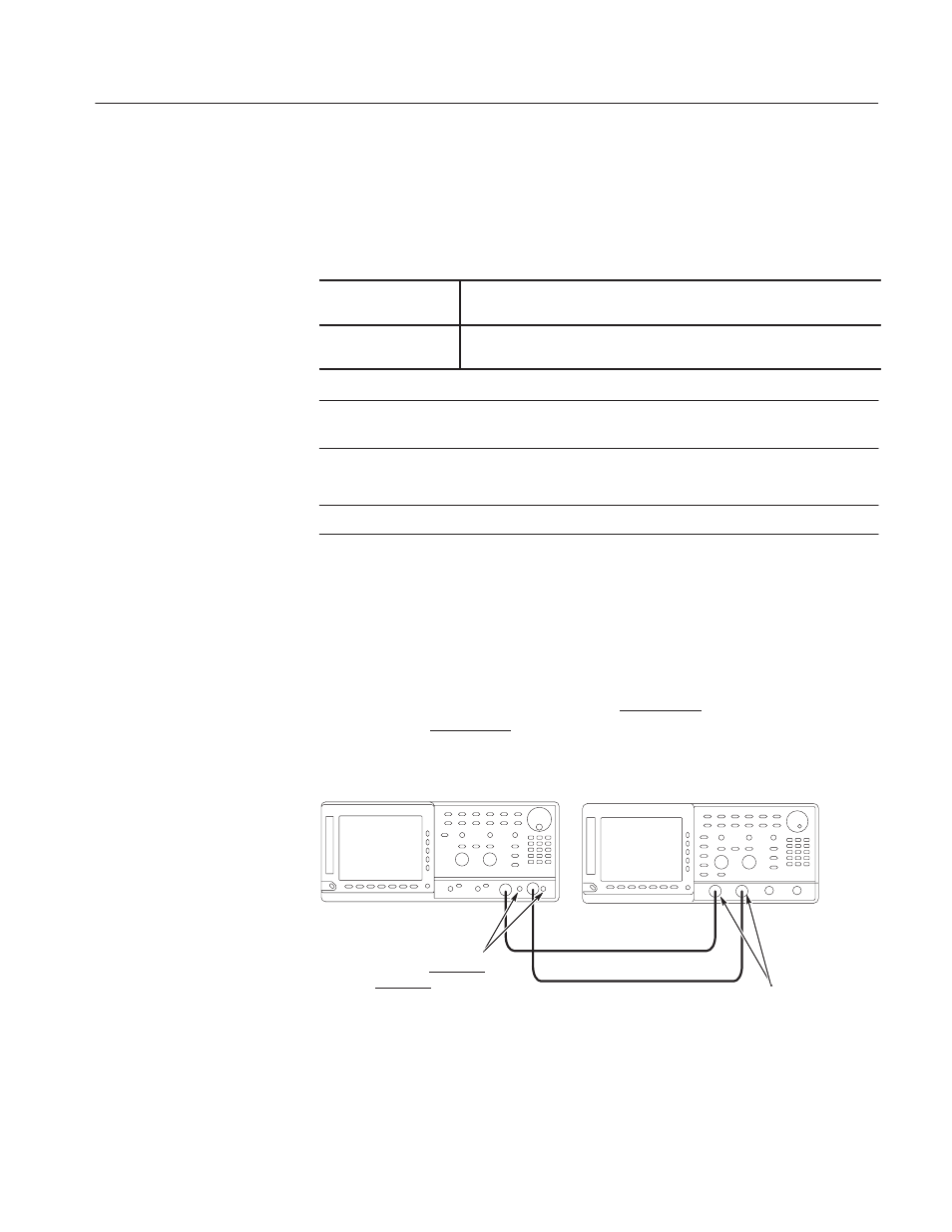
Do the following steps to install the test hookup and set the test equipment
controls:
1. Use the 50
W
SMA coaxial cables and SMA-to-BNC adapters to connect the
AWG610 Arbitrary Waveform Generator MARKER1 and MARKER2
outputs to the oscilloscope CH1 and CH2 input connectors (see
Figure B–32).
2. Connect a 50
WĂSMA terminator to the MARKER1 and a 50 WĂSMA termi-
nator to the MARKER2 connectors.
ББ
ББ
50 W SMA coaxial cable
50 W SMA coaxial cable
AWG610 Arbitrary Waveform Generator
ConnectĂ50 WĂSMA
terminators to the MARKER1
andMARKER2 connector
OscilloscopeĂ(TDS700)
SMA(Fe)ĆBNC(Ma)
adapters
Figure B-32: Marker delaytest hookup