Tektronix AWG610 User Manual
Page 381
Appendix B: Performance Verification
AWG610 Arbitrary Waveform Generator User Manual
B-21
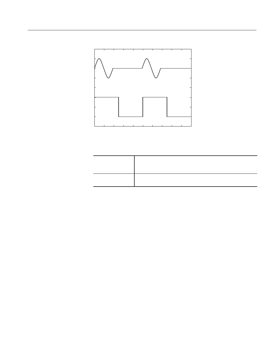
Waveform
output CH1
Trigger
signal
CH2
Figure B-7: Relationship between trigger signal and waveform output
Equipment
required
Two 50ĂW BNCĂcoaxial cables, aĂ50ĂW SMAĂcoaxial cable,
ĂaĂSMA(Fe)ĆBNC(Ma)Ăadapter,ĂaĂBNCĆTĂ(male to 2 females) adapter, a
function generator, and an oscilloscopeĂ(TDS700).
Prerequisites
The AWG610 Arbitrary Waveform Generator must meet the
prerequisites listed on page B-8.
1. Set the oscilloscope controls as follows:
Vertic al . . . . . . . . . . . . . . . . . . . . . . . . . CH1 and CH2
CH1 and CH2 coupling . . . . . . . . . DC
CH1 sc ale . . . . . . . . . . . . . . . . . . 0.5 V/div
CH2 sc ale . . . . . . . . . . . . . . . . . . 2 V/div
CH1 input impedance . . . . . . . . . . 50 W
CH2 input impedance . . . . . . . . . . 1 MW
Horizontal
Sweep . . . . . . . . . . . . . . . . . . . . . 20 ms/div
Trigger
Source . . . . . . . . . . . . . . . . . . . . . CH1
Coupling . . . . . . . . . . . . . . . . . . . . AC
Slope . . . . . . . . . . . . . . . . . . . . . . Positive
Level . . . . . . . . . . . . . . . . . . . . . . 0 V
Mode . . . . . . . . . . . . . . . . . . . . . . Auto
2. Set the function generator (AFG310) controls as follows:
Check Gated Mode