Operating mode tests – Tektronix AWG610 User Manual
Page 377
Appendix B: Performance Verification
AWG610 Arbitrary Waveform Generator User Manual
B-17
Operating Mode Tests
The following procedures verify the operation of the Cont, Triggered and Gated
modes.
NOTE. When you output signal from the CH1 or CH1 OUTPUT, check that the
other OUTPUT ( CH1 or CH1 ) LED is off.
If the other OUTPUT LED is on, push the CH1 or CH1 OUT button to turn off
the output.
Equipment
required
A 50 W SMAĂcoaxial cable,ĂaĂSMA(Fe)ĆBNC(Ma)Ăadapter and an
oscilloscopeĂ(TDS700).
Prerequisites
The AWG Arbitrary Waveform Generator must meet the prerequisites
listedon page B-8.
Do the following steps to install the test hookup and set the test equipment
controls:
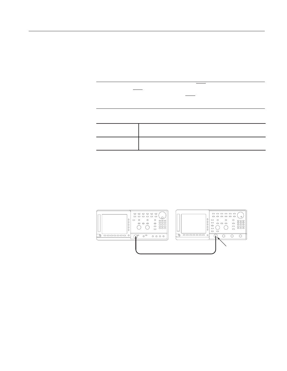
1. Use a 50
W
coaxial cable to
c
onnect the AWG610 Arbitrary Waveform
Generator CH1 output connector to the oscilloscope CH1 input connector
(see Figure B–5).
OscilloscopeĂ(TDS700)
50 W SMAĂcoaxial cable
AWG610 Arbitrary Waveform Generator
SMA(Fe)ĆBNC(Ma)
adapter
ББ
ББ
Figure B-5: Cont mode initial test hookup
2. Set the oscilloscope controls as follows:
Vertical . . . . . . . . . . . . . . . . . . . . . . . . . CH1
CH1 coupling . . . . . . . . . . . . . . . . DC
CH1 scale . . . . . . . . . . . . . . . . . . 0.2 V/d iv
CH1 input impedance . . . . . . . . . . 50 W
Horizontal
Sweep . . . . . . . . . . . . . . . . . . . . . 200 ns/div
Check Cont Mode