Tektronix AWG610 User Manual
Page 404
Appendix B: Performance Verification
B-44
AWG610 Arbitrary Waveform Generator User Manual
d. Push Cursor,
%, &, , keys as the low level of a pulse to be set to
–5.35V.
e.
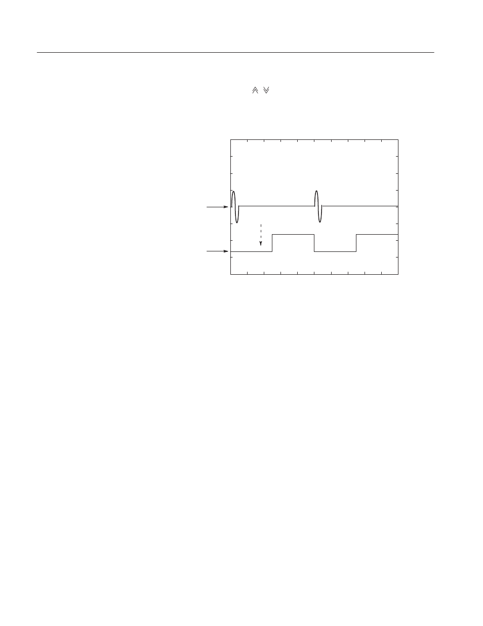
Verify that a sine wave is displayed on the oscilloscope.
Trigger Signal CH2
(-5.35 V level)
CH1
Figure B-19: Trigger Signal (-5V check2)
9. Push the RUN button to turn off the RUN LED.
10. Disconnect all the cable.