Tektronix AWG610 User Manual
Page 389
Appendix B: Performance Verification
AWG610 Arbitrary Waveform Generator User Manual
B-29
Amplitude, Offset Accuracy and Rise Time Tests (Direct DA Out)
These procedures check the accuracy of the AWG610 Arbitrary Waveform
Generator direct waveform outputs; amplitude and offset.
Equipment
required
A 50ĂW BNCĂcoaxial cable, a 50ĂWĂprecision terminator, an
SMA(Fe)-BNC(Ma) adapter,
BNC (female)ĆtoĆdual banana
adapter, and a digital multimeter (DMM).
Prerequisites
The AGW610 Arbitrary Waveform Generator must meet the
prerequisites listedon page B-8.
Do the following steps to install the test hookup and set the test equipment
controls:
1. Use a 50
W
BNC coaxial cable, an SMA(Fe)-BNC(Ma) adapter, a 50
W
precision terminator, and a BNC-to-dual banana adapter to connect the
AWG610 Arbitrary Waveform Generator CH1 output to the DMM input
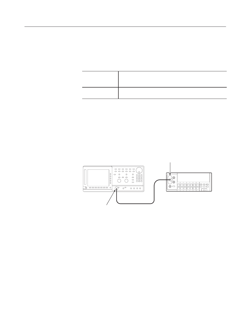
connector (see Figure B–10).
ББ
ББ
DMM
50 W BNCĂcoaxial cable
InputĂconnector
+ĂBNCĆtoĆdual banana adapter
+Ă50 W BNCĂcoaxialĂcable
AWG610 Arbitrary Waveform Generator
CH1ĂoutputĂconnector
+ĂSMA(Fe)ĆBNC(Ma) adapter
+ĂBNC 50 WĂprecision terminator
+Ă50 WĂBNC coaxial cable
Figure B-10: Direct DA output amplitude accuracy initial test hookup
2. Set the DMM controls as follows:
Mod e . . . . . . . . . . . . . . . . . . . . . . . . . . VDC
Range . . . . . . . . . . . . . . . . . . . . . . . . . 2 V
Input . . . . . . . . . . . . . . . . . . . . . . . . . . Front
Check Amplitude
and
DC Offset