Marker output tests – Tektronix AWG610 User Manual
Page 418
Appendix B: Performance Verification
B-58
AWG610 Arbitrary Waveform Generator User Manual
Marker Output Tests
These procedures check the accuracy of the AWG610 Arbitrary Waveform
Generator marker output level.
Equipment
required
A 50ĂW SMA coaxial cable, anĂSMA(Fe)ĆBNC(Ma) adaptĆ
er,ĂaĂ50ĂWĂSMAĂterminator,Ăand an oscilloscope.
Prerequisites
The
AWG610 Arbitrary Waveform Generator
must meet the
prerequisites listed on page B-8.
NOTE. Connect a 50W SMA terminator to the inverted marker output connector
during the marker output tests.
Do the following steps to install the test hookup and set the test equipment
controls:
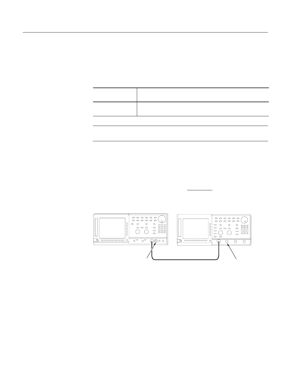
1. Use an SMA coaxial cable and an SMA-to-BNC adapter to connect the
AWG610 Arbitrary Waveform Generator MARKER1 connector to the
oscilloscope CH1 input connector (see Figure B–31).
2. Connect a 50
WĂSMA terminator to the MARKER1 connector.
ББ
ББ
AWG610 Arbitrary Waveform Generator
50 W SMA coaxial cable
50 WĂSMA terminator
OscilloscopeĂ(TDS700)
SMA(Fe)ĆBNC(Ma)
adapter
Figure B-31: Marker output initial test hookup
3. Set the oscilloscope controls as follows:
Vertical . . . . . . . . . . . . . . . . . . . . . . . . . CH1
CH1 coupling . . . . . . . . . . . . . . . . DC
CH1 scale. . . . . . . . . . . . . . . . . . 1 V/div
CH1 input impedance . . . . . . . . . . 50 W
CH1 offse t . . . . . . . . . . . . . . . . . . 0 V