Pulse response tests – Tektronix AWG610 User Manual
Page 394
Appendix B: Performance Verification
B-34
AWG610 Arbitrary Waveform Generator User Manual
Pulse Response Tests
This procedure checks the pulse response characteristics of the AWG610
Arbitrary Waveform Generator output waveforms at amplitudes of 1 V.
Equipment
required
A 50ĂW SMAĂcoaxial cable and an oscilloscope (TDS820).
Prerequisites
The AWG610 Arbitrary Waveform Generator must meet the
prerequisites listed on page B-8.
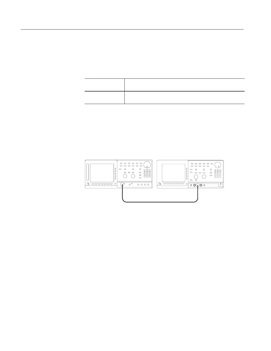
Do the following steps to install the test hookup and set the test equipment
controls:
1. Use the 50
W SMA coaxial cable to connect the AWG610 Arbitrary
Waveform Generator CH1 output connector to the oscilloscope CH1 input
connector (see Figure B–12).
ББ
ББ
AWG610 Arbitrary Waveform Generator
Oscilloscope (TDS820)
50 W SMAĂcoaxial cable
Figure B-12: Pulse response initial test hookup
2. Set the oscilloscope controls as follows:
Vertical . . . . . . . . . . . . . . . . . . . . . . . . . CH1
CH1 coupling . . . . . . . . . . . . . . . . DC if applicable
CH1 scale . . . . . . . . . . . . . . . . . . 250 mV/div (200 mV for TDS820)
Horizontal
Sweep . . . . . . . . . . . . . . . . . . . . . 500 ps/div
Trigger
Source . . . . . . . . . . . . . . . . . . . . . CH1
Slope . . . . . . . . . . . . . . . . . . . . . . Positive
Level . . . . . . . . . . . . . . . . . . . . . . 0 V
Mode . . . . . . . . . . . . . . . . . . . . . . Auto