1/4 clock output ălevelătests – Tektronix AWG610 User Manual
Page 414
Appendix B: Performance Verification
B-54
AWG610 Arbitrary Waveform Generator User Manual
1/4 Clock Output ĂLevelĂTests
These procedures check the AWG610 Arbitrary Waveform Generator clock
output signal.
Equipment
required
A 50ĂW BNC coaxial cable and an oscilloscope.
Prerequisites
The AWG610 Arbitrary Waveform Generator must meet the
prerequisites listed on page B-8.
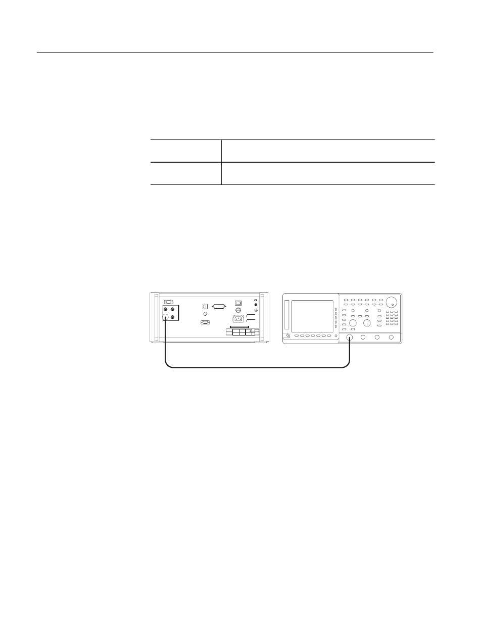
Do the following steps to install the test hookup and set the test equipment
controls:
1. Use the 50
W
BNC coaxial cable to connect the AWG610 Arbitrary
Waveform Generator 1/4 CLOCK OUT output to the oscilloscope input
connector (see Figure B–29).
AWG610 Arbitrary Waveform
Generator rear panel
OscilloscopeĂ(TDS700)
50 W BNCĂcoaxial cable
1/4ĂCLOCKĂOUT
Figure B-29: 1/4 Clock output level initial test hookup
2. Set the oscilloscope controls as follows:
Vertical . . . . . . . . . . . . . . . . . . . . . . . . . CH1
CH1 coupling . . . . . . . . . . . . . . . . DC
CH1 sca le . . . . . . . . . . . . . . . . . . 0.5 V/div
CH1 offset . . . . . . . . . . . . . . . . . . Ć1.3 V
CH1 input impedance . . . . . . . . . . 1 MW
Horizontal
Sweep . . . . . . . . . . . . . . . . . . . . . 5 ns/div
Trigger
Source . . . . . . . . . . . . . . . . . . . . . CH1
Coupling . . . . . . . . . . . . . . . . . . . . AC
Slope . . . . . . . . . . . . . . . . . . . . . . Positive
Level . . . . . . . . . . . . . . . . . . . . . . 0 V
Mode . . . . . . . . . . . . . . . . . . . . . . Auto