Tektronix AWG610 User Manual
Page 379
Appendix B: Performance Verification
AWG610 Arbitrary Waveform Generator User Manual
B-19
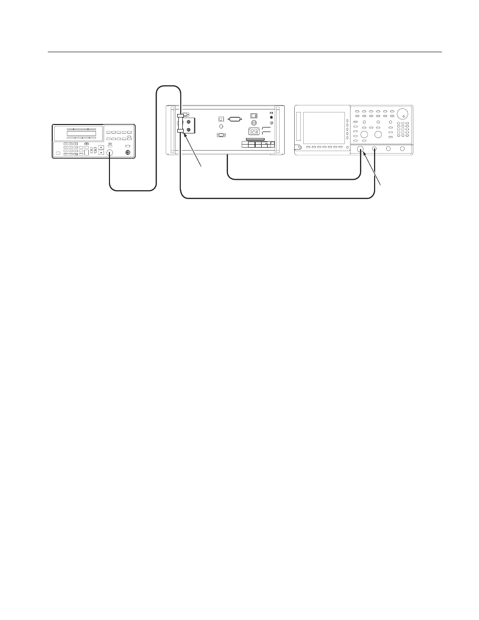
BNC T
Adapter
AWG610 Arbitrary Waveform
Generator rear panel
Output
CH2 input
CH1 input
CH1 output
OscilloscopeĂ(TDS700)
SMA(Fe)ĆBNC(Ma)
adapter
50 W SMAĂcoaxial cable
50 W BNCĂcoaxial cable
50 W BNCĂcoaxial cable
Function Generator (AFG310)
Figure B-6: Triggered mode initial test hookup
4. Set the oscilloscope controls as follows:
Vertical . . . . . . . . . . . . . . . . . . . . . . . . . CH1 and CH2
CH1 coupling . . . . . . . . . . . . . . . . DC
CH1 scale . . . . . . . . . . . . . . . . . . 0.5 V/div
CH2 scale . . . . . . . . . . . . . . . . . . 2 V/div
CH1 input impedance . . . . . . . . . . 50 W
CH2 input impedance . . . . . . . . . . 1 MW
Horizontal
Sweep . . . . . . . . . . . . . . . . . . . . . 200 ns/div
Trigger
Source . . . . . . . . . . . . . . . . . . . . . CH1
Coupling . . . . . . . . . . . . . . . . . . . . DC
Slope . . . . . . . . . . . . . . . . . . . . . . Positive
Level . . . . . . . . . . . . . . . . . . . . . . +100 mV
Mode . . . . . . . . . . . . . . . . . . . . . . NORMAL