3 connectors and indicators, 1 connectors and indicators on the system board, 1 onboard connectors – FUJITSU PRIMERGY MX130 S2 User Manual
Page 249: Connectors and indicators, Connectors and indicators on the system board, Onboard connectors, Upgrade and maintenance manual 249 appendix
MX130 S2
Upgrade and Maintenance Manual
249
Appendix
15.3 Connectors and indicators
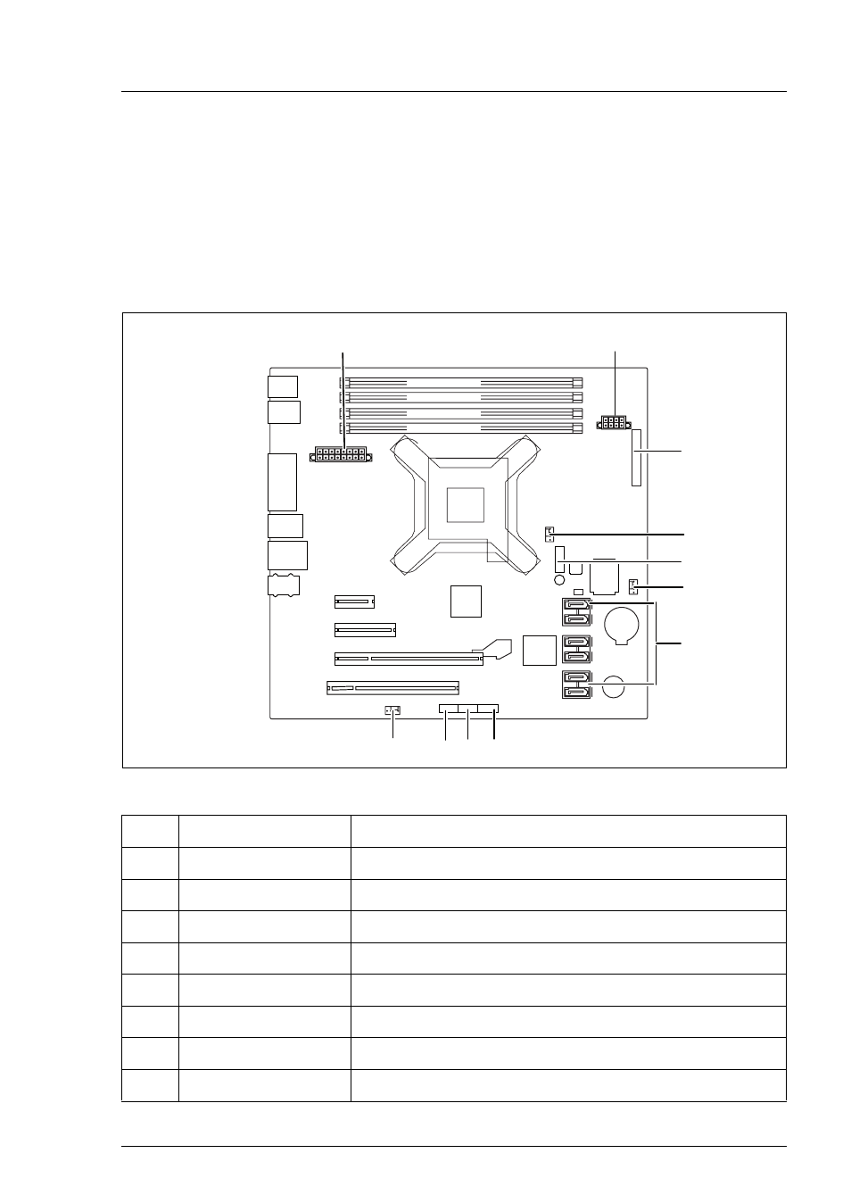
15.3.1 Connectors and indicators on the system board
15.3.1.1 Onboard connectors
Figure 160: Internal connectors of the system board D3090
No. Print
Description
1
POWER12V
ATX power supply connector
2
POWER SATA
Power distribution for HDDs and accessible drives
3
FRONT PANEL
Front panel
4
FAN1
CPU fan
5
TPM
Connector for Trusted Platform Module (TPM)
6
FAN2 System
fan
7
SATA 1-6
SATA connectors drive configurations
8
USB-FRONT 1/2
USB connector for front USB board
Battery
PCI
SATA 3+4
SATA 5+6
POWER 12V
PCI-E x16
PCI-E x4
PCI-Ex1
Northbridge
AM3/AM3+
CPU
Southbridge
F
AN2
F
AN1
Super
I/O
TPM
Dash
USB 5/6
Intrusion
USB-FRONT
3/4
USB-FRONT
1/2
FRONT
P
ANEL
Audio
PS2
COM
DVI-I
USB
11+12
USB
9+10
LAN/
USB
7+8
Buzzer
SATA
1+2
Module 2 Channel B
Module 4 Channel B
Module 1 Channel A
Module 3 Channel A
optional)
(optional)
(optional)
0
1
2
3
4
5
6
7
8
9
/
POWER SATA