Grass Valley XtenDD v.4.2.4 User Manual
Page 350
3. Menu Operation
3 – 203
Operating Instructions – Rev. 1 / 7.2002
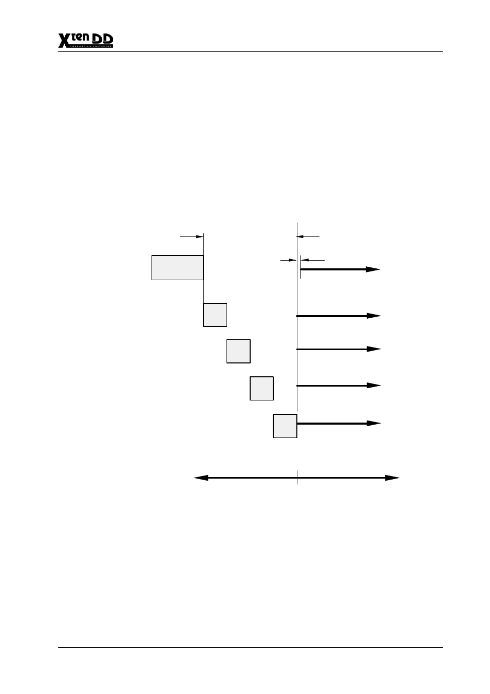
3.15.2.3 Timing Adjustment XtenDD
When source signals are fed into the switcher, it must be ensured that the time dif-
ference between the sources is not outside the operating range of the internal
switcher autophasers (41
µ
s). The output signals of the sources must correspond to
the timing customary in operation. For instance, no EE picture in a VTR, PB-Ref on
CCVS etc.
The switcher’s Genlock Phase can be adjusted to the fed reference signal in the
range of –9 line to +10 lines.
Autophasing
ME1
approx 41us
approx 5.6us
Min delay
approx 0.6us
Aux outputs
ME3 output, PVW
Timing reference diagram
ME2
approx 5.6us
ME3
approx 5.6us
ME2 output, PVW
Main outputs, PVW
approx 41 us
Total timing position of XtenDD in respect to reference blackburt:
approx minus 9 lines
approx plus 9 lines
PP
approx 5.6us
ME1 outputs, PVW
range inputs
Refer to the Installation Manual for detailed information for DD35-2
and DD35-3 switchers.
- LDK 5302 (24 pages)
- SFP Optical Converters (18 pages)
- 2000GEN (22 pages)
- 2011RDA (28 pages)
- 2010RDA-16 (28 pages)
- 2000NET v3.2.2 (72 pages)
- 2000NET v3.1 (68 pages)
- 2020DAC D-To-A (30 pages)
- 2000NET v4.0.0 (92 pages)
- 2020ADC A-To-D (32 pages)
- 2030RDA (36 pages)
- 2031RDA-SM (38 pages)
- 2041EDA (20 pages)
- 2040RDA (24 pages)
- 2041RDA (24 pages)
- 2042EDA (26 pages)
- 2090MDC (30 pages)
- 2040RDA-FR (52 pages)
- LDK 4021 (22 pages)
- 3DX-3901 (38 pages)
- LDK 4420 (82 pages)
- LDK 5307 (40 pages)
- Maestro Master Control Installation v.1.5.1 (455 pages)
- Maestro Master Control Installation v.1.5.1 (428 pages)
- 7600REF Installation (16 pages)
- 7600REF (84 pages)
- 8900FSS (18 pages)
- 8900GEN-SM (50 pages)
- 8900NET v.4.3.0 (108 pages)
- Safety Summary (17 pages)
- 8900NET v.4.0.0 (94 pages)
- 8906 (34 pages)
- 8911 (16 pages)
- 8900NET v.3.2.2 (78 pages)
- 8914 (18 pages)
- 8912RDA-D (20 pages)
- 8916 (26 pages)
- 8910ADA-SR (58 pages)
- 8920ADC v.2.0 (28 pages)
- 8920ADC v.2.0.1A (40 pages)
- 8920DAC (28 pages)
- 8920DMX (30 pages)
- 8920ADT (36 pages)
- 8920MUX (50 pages)
- 8921ADT (58 pages)