Configuration procedure – H3C Technologies H3C SR8800 User Manual
Page 92
80
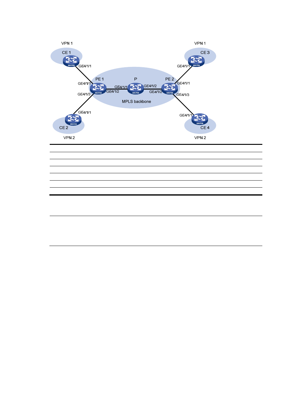
Figure 31 Network diagram
Device Interface IP
address
Device Interface IP
address
CE 1
GE4/1/1
10.1.1.1/24
PE 1
GE4/1/1 10.1.1.2/24
CE 2
GE4/1/1
10.2.1.1/24
GE4/1/2 172.1.1.1/24
CE
3
GE4/1/1 10.3.1.1/24
GE4/1/3 10.2.1.2/24
CE 4
GE4/1/1
10.4.1.1/24
PE 2
GE4/1/1 10.3.1.2/24
P GE4/1/1
172.1.1.2/24
GE4/1/2 172.2.1.2/24
GE4/1/2 172.2.1.1/24
GE4/1/3 10.4.1.2/24
Configuration procedure
NOTE:
Prior to performing the following configuration, be sure you have completed MPLS VPN-related
configurations and make sure of the reachability between CE 1 and PE 1, between PE 1 and PE 2, and
between PE 2 and CE 3. For more information about MPLS VPN, see
MPLS Configuration Guide.
1.
Set the IP address for each interface as shown in
. (Details not shown)
2.
Configure CE 1:
# Specify the local clock as the reference source, with the stratum level of 1.
[CE1] ntp-service refclock-master 1
3.
Configure CE 3:
# Specify CE 1 in VPN 1 as the NTP server of CE 3.
[CE3] ntp-service unicast-server 10.1.1.1
# View the NTP session information and status information on CE 3 a certain period of time later.
The information should show that CE 3 has been synchronized to CE 1, with the clock stratum level
of 2.
[CE3] display ntp-service status
Clock status: synchronized
Clock stratum: 2
- H3C SR6600-X H3C SR6600 H3C SecPath F5020 H3C SecPath F5040 H3C VMSG VFW1000 H3C WX3000E Series Wireless Switches H3C WX5500E Series Access Controllers H3C WX3500E Series Access Controllers H3C WX2500E Series Access Controllers H3C WX6000 Series Access Controllers H3C WX5000 Series Access Controllers H3C LSWM1WCM10 Access Controller Module H3C LSUM3WCMD0 Access Controller Module H3C LSUM1WCME0 Access Controller Module H3C LSWM1WCM20 Access Controller Module H3C LSQM1WCMB0 Access Controller Module H3C LSRM1WCM2A1 Access Controller Module H3C LSBM1WCM2A0 Access Controller Module