Configuration procedure – H3C Technologies H3C SR8800 User Manual
Page 140
128
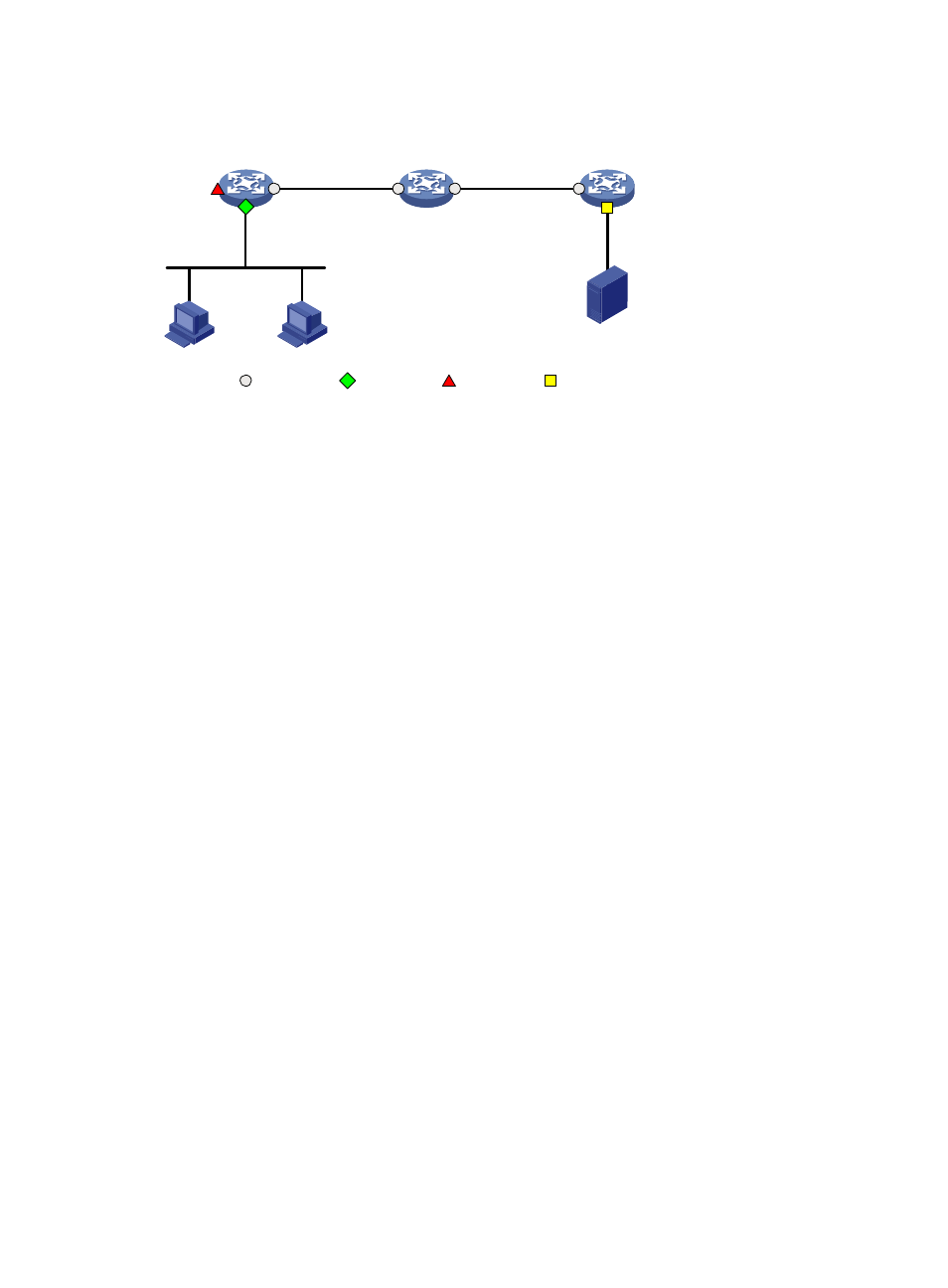
Figure 48 Network diagram
Configuration procedure
1.
Configure Device A (the source device):
# Create a remote source group.
[DeviceA] mirroring-group 1 remote-source
# Create VLAN 2.
[DeviceA] vlan 2
[DeviceA-vlan2] quit
# Configure VLAN 2 as the remote probe VLAN, GigabitEthernet 3/0/1 as a source port, and
GigabitEthernet 3/0/3 as the reflector port in the mirroring group.
[DeviceA] mirroring-group 1 remote-probe vlan 2
[DeviceA] mirroring-group 1 mirroring-port GigabitEthernet3/0/1 both
[DeviceA] mirroring-group 1 reflector-port GigabitEthernet3/0/3
# Configure GigabitEthernet 3/0/2 as a trunk port that permits the packets of VLAN 2 to pass
through.
[DeviceA] interface GigabitEthernet3/0/2
[DeviceA-GigabitEthernet3/0/2] port link-type trunk
[DeviceA-GigabitEthernet3/0/2] port trunk permit vlan 2
[DeviceA-GigabitEthernet3/0/2] quit
# Disable the spanning tree feature on reflector port GigabitEthernet 3/0/3.
[DeviceA] interface GigabitEthernet3/0/3
[DeviceA-GigabitEthernet3/0/3] undo stp enable
[DeviceA-GigabitEthernet3/0/3] quit
2.
Configure Device B (the intermediate device):
# Create VLAN 2.
[DeviceB] vlan 2
[DeviceB-vlan2] quit
# Configure GigabitEthernet 3/0/1 as a trunk port that permits the packets of VLAN 2 to pass
through.
[DeviceB] interface GigabitEthernet3/0/1
[DeviceB-GigabitEthernet3/0/1] port link-type trunk
Source device
Device A
GE3/0/1
GE3/0/2
Server
Marketing
Dept.
Intermediate device
Device B
Destination device
Device C
GE3/0/1
GE3/0/2
GE3/0/1
GE3/0/2
Source port
Monitor port
Reflector port
Common port
GE3/0/3
- H3C SR6600-X H3C SR6600 H3C SecPath F5020 H3C SecPath F5040 H3C VMSG VFW1000 H3C WX3000E Series Wireless Switches H3C WX5500E Series Access Controllers H3C WX3500E Series Access Controllers H3C WX2500E Series Access Controllers H3C WX6000 Series Access Controllers H3C WX5000 Series Access Controllers H3C LSWM1WCM10 Access Controller Module H3C LSUM3WCMD0 Access Controller Module H3C LSUM1WCME0 Access Controller Module H3C LSWM1WCM20 Access Controller Module H3C LSQM1WCMB0 Access Controller Module H3C LSRM1WCM2A1 Access Controller Module H3C LSBM1WCM2A0 Access Controller Module