Configuration procedure – H3C Technologies H3C SR8800 User Manual
Page 90
78
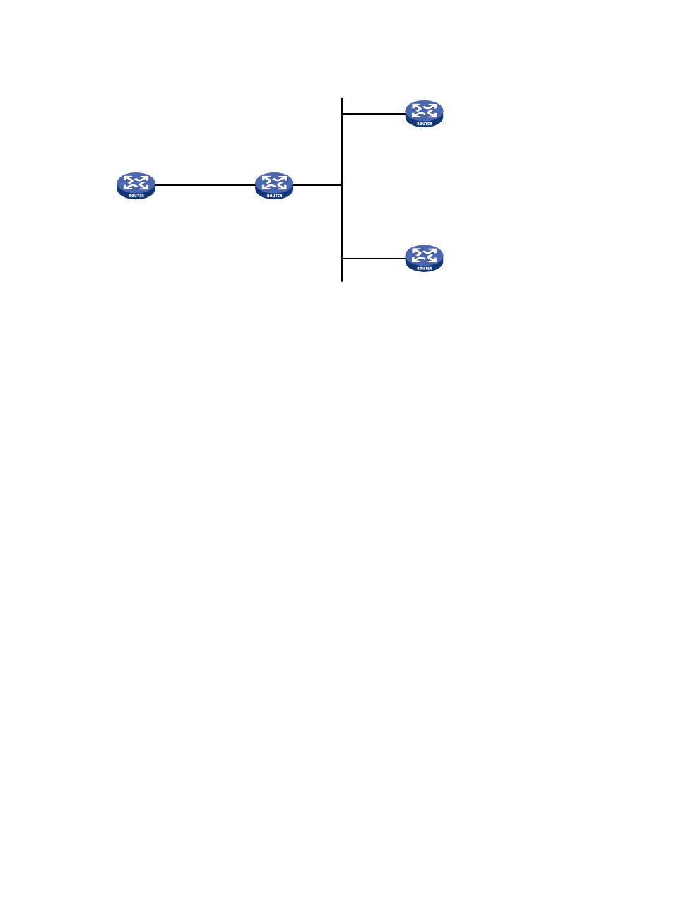
Figure 30 Network diagram
Configuration procedure
1.
Set the IP address for each interface as shown in
. (Details not shown)
2.
Configure Router C:
# Specify the local clock as the reference source, with the stratum level of 3.
[RouterC] ntp-service refclock-master 3
# Configure NTP authentication
[RouterC] ntp-service authentication enable
[RouterC] ntp-service authentication-keyid 88 authentication-mode md5 123456
[RouterC] ntp-service reliable authentication-keyid 88
# Specify Router C as an NTP broadcast server, and specify an authentication key.
[RouterC] interface GigabitEthernet 3/1/10
[RouterC-GigabitEthernet3/1/10] ntp-service broadcast-server authentication-keyid
88
3.
Configure Router D:
# Configure NTP authentication
[RouterD] ntp-service authentication enable
[RouterD] ntp-service authentication-keyid 88 authentication-mode md5 123456
[RouterD] ntp-service reliable authentication-keyid 88
# Configure Router D to work in the NTP broadcast client mode
[RouterD] interface GigabitEthernet 3/1/10
[RouterD-GigabitEthernet3/1/10] ntp-service broadcast-client
Now, Router D can receive broadcast messages through GigabitEthernet 3/1/10, and Router C
can send broadcast messages through GigabitEthernet 3/1/10. Upon receiving a broadcast
message from Router C, Router D synchronizes its clock with that of Router C.
# View the NTP status of Router D after clock synchronization.
[RouterD-GigabitEthernet3/1/10] display ntp-service status
Clock status: synchronized
Clock stratum: 4
Reference clock ID: 3.0.1.31
GE3/1/1
1.0.1.10/24
Router A
GE3/1/10
3.0.1.31/24
GE3/1/10
3.0.1.32/24
Router B
Router C
Router D
GE3/1/10
1.0.1.11/24
GE3/1/10
3.0.1.30/24
- H3C SR6600-X H3C SR6600 H3C SecPath F5020 H3C SecPath F5040 H3C VMSG VFW1000 H3C WX3000E Series Wireless Switches H3C WX5500E Series Access Controllers H3C WX3500E Series Access Controllers H3C WX2500E Series Access Controllers H3C WX6000 Series Access Controllers H3C WX5000 Series Access Controllers H3C LSWM1WCM10 Access Controller Module H3C LSUM3WCMD0 Access Controller Module H3C LSUM1WCME0 Access Controller Module H3C LSWM1WCM20 Access Controller Module H3C LSQM1WCMB0 Access Controller Module H3C LSRM1WCM2A1 Access Controller Module H3C LSBM1WCM2A0 Access Controller Module