Example for configuring kompella mpls l2vpn, Network requirements – H3C Technologies H3C S7500E Series Switches User Manual
Page 219
5-27
After completing the above configurations, you can display L2VPN connection information on PE 1 or
PE 2. There should be one L2VC established. CE 1 and CE 2 should be able to ping each other.
# Display L2VPN connection information on PE 1.
[PE1] display mpls l2vc
Total ldp vc : 1 1 up 0 down
Transport Client VC Local Remote Tunnel
VC ID Intf State VC Label VC Label Policy
101 Vlan10 up 8193 8192 default
# Display L2VPN connection information on PE 2.
[PE2] display mpls l2vc
Total ldp vc : 1 1 up 0 down
Transport Client VC Local Remote Tunnel
VC ID Intf State VC Label VC Label Policy
101 Vlan10 up 8192 8193 default
# Ping CE 2 from CE 1.
[CE1] ping 100.1.1.2
PING 100.1.1.2: 56 data bytes, press CTRL_C to break
Reply from 100.1.1.2: bytes=56 Sequence=1 ttl=255 time=30 ms
Reply from 100.1.1.2: bytes=56 Sequence=2 ttl=255 time=60 ms
Reply from 100.1.1.2: bytes=56 Sequence=3 ttl=255 time=50 ms
Reply from 100.1.1.2: bytes=56 Sequence=4 ttl=255 time=40 ms
Reply from 100.1.1.2: bytes=56 Sequence=5 ttl=255 time=70 ms
--- 100.1.1.2 ping statistics ---
5 packet(s) transmitted
5 packet(s) received
0.00% packet loss
round-trip min/avg/max = 30/50/70 ms
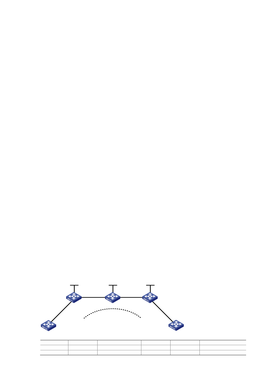
Example for Configuring Kompella MPLS L2VPN
Network requirements
z
CEs are connected to PEs through VLAN interfaces.
z
A Kompella MPLS L2VPN is established between CE 1 and CE 2.
Figure 5-6
Network diagram for configuring Kompella MPLS L2VPN
Vlan-int20
Vlan-int20
Loop0
Vlan-int30
Vlan-int30
Vlan-int10
Vlan-int10
Vlan-int10
Vlan-int10
Loop0
Loop0
PE 1
PE 2
P
CE 1
CE 2
Kompella
Device Interface IP
address
Device Interface
IP
address
CE 1
Vlan-int10
100.1.1.1/24 P
Loop0
3.3.3.3/32
PE 1
Loop0
2.2.2.2/32
Vlan-int20 10.1.1.2/24