Measurement Computing eZ-Analyst rev.14.1 User Manual
Page 54
4-18 Edit Menu
978791
eZ-Analyst
Tachometer Section of the Input Channels Tab, 2
nd
5 Columns
Edge
Detect
Edge Detect
– Edge Detect is short for “Tach Pulse Edge Detection.” The
term pertains to detecting the rising or falling edge of a tachometer pulse using
either an “Immediate” or “Delayed” mode.
Immediate Edge Detection
(“Before Stable”)
– “Immediate” is one of two
Edge Detect modes. The term is synonymous with “Before Stable.” If
“Immediate” edge detection is selected a tach pulse will be recognized on any
instantaneous measurement that meets the trigger level criteria. In this setup
the “Delay Value” is the amount of time before the next tach pulse can be
recognized.
Delayed Edge Detection
(“After Stable”)
– “Delayed” is one of two Edge
Detect modes. The term is synonymous with “After Stable.” If “Delayed” edge
detection is selected a tach pulse will be recognized when the measurement
meets the trigger criteria for the specified duration. In this setup the “Delay
Value” defines the length of time that the trigger criteria must be stable before
the tach pulse will be recognized. If a keyway is being used as a tach trigger you
must calculate the minimum pulse width, based on the maximum RPM rate
expected.
Delay
Time
One of several time settings between 500 ns and 25.5 ms. The delay time is
used in conjunction with edge detect and is used to optimize noise rejection.
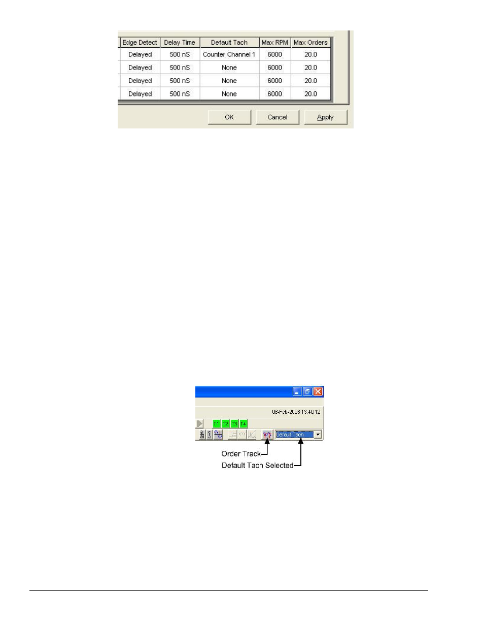
Default
Tach
If “Default Tach” is selected from the tach channel combo-box [next to the Order
Track button] on the toolbar (following figure), then the tach channel shown in
this column is the one that will be used when calculating orders.
Max RPM
and
Max
Orders
Max RPM and Max Orders are used to limit the X axes scale range when
calculating an Order Tracking display in the main function view window. Max
RPM and Max Orders represent the practical limits of the Order Track display that
are constrained by the settings of Analysis frequency, Spectral lines, and the
Nyquist Factor. These two values interact. Changing one will cause the other to
change.