Measurement Computing eZ-Analyst rev.14.1 User Manual
Page 41
eZ-Analyst
978791
Edit Menu 4-5
Edit Menu > Configuration >
Analyzer Tab:
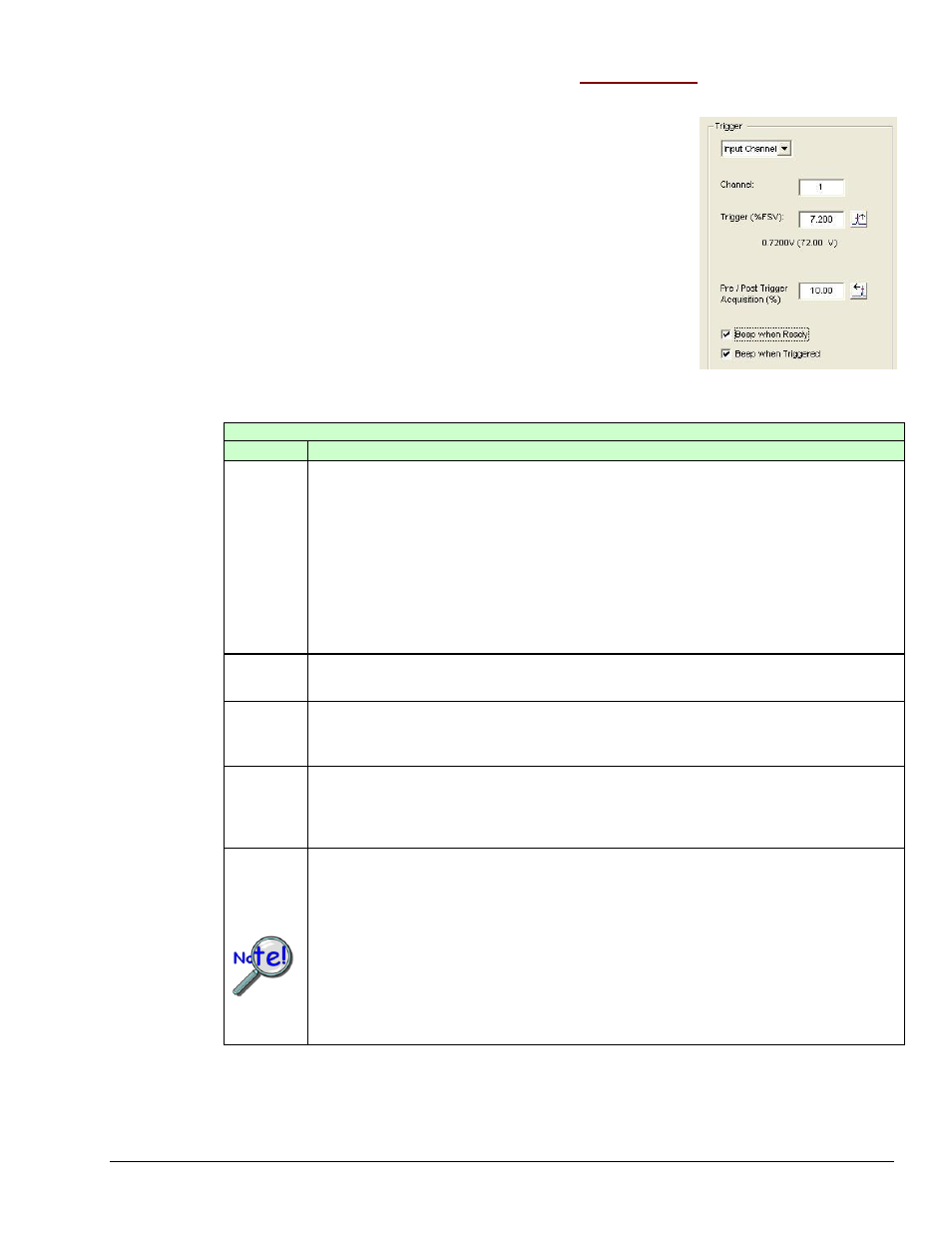
Trigger Panel
The Trigger Panel provides a means of setting and defining trigger-related parameters.
Triggering defines how eZ-Analyst is to begin the task of
capturing and processing data. To capture data without
using a trigger, select Free Run from the pull-down list. To
capture transient data, select Input Channel from the pull-
down list and set values for the applicable parameters.
Trigger Panel
on the Analyzer Tab
A Breakdown of the Analyzer Tab’s Trigger Panel
Category
Description
Type
If “Free Run” is selected as the Type, the data acquisition and processing will
begin as soon as the
to measure data in a continuous or Scope mode manner [from an active system].
If “Input Channel” is selected as the Type, the data acquisition and processing
begin after the signal on the specified channel reaches the defined trigger
conditions. Select “Input Channel” if you want to capture transient data.
“TTL Pulse” applies to the TRIGGER INPUT BNC on ZonicBook/618E and to the
TTL TRIGGER on WaveBook’s DB25 connector (pin # 13). The input accepts a 0
to 5 V TTL compatible signal. Latency is 300 ns.
Channel
No.
Specifies the channel that the trigger condition applies to.
Level
This value is the point that the signal must pass through to be considered as a
candidate for a trigger. This value is entered as volts and must be within the
selected FSV.
Slope
Slope icon buttons are used to select a “Positive” rising (up arrow) or a
“Negative” falling (down arrow) slope of the signal that defines a trigger
condition. The signal must be on the defined slope before it can be considered
for use as a trigger
Pre-
Trigger
Selecting the “Pre-Trigger” icon button (arrow will point left) instructs the
system to capture a specified percentage of data [a specified percent of the
frame size] prior to the start of trigger event. In the previous figure we see that
“Pre-Trigger” is selected for 10.00 (%).
Note: For 640 and 650 series devices a maximum pre-trigger percentage for
exists for each combination of analysis frequency, number of spectral
lines, and number of analog input channels. Entering too high of a
percentage results in an error message. You can use the following 5
tables to see the allowed maximum pre-trigger percentage for your
configuration.