Figure 8), 5 opw 7h, 6 zva 25 – Gasboy Fuel Point PLUS Station User Manual
Page 132
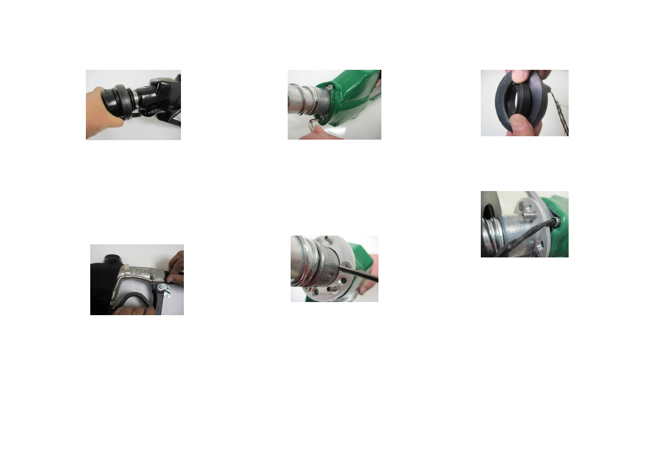
Figure 8. Checking Compression of the Bellows
Thread the coil wire through the Flexible
Conduit and then through the Rigid Conduit.
Flexible Conduit P/N 815900209 (7cm) is
provided for Healy 600/700/800/900 models,
while P/N 815900204 (0.5m) is provided for
Healy 400 only
Secure the conduit using both the front and the
back clip as shown in Figure 9
Figure 9. Securing the Rigid Conduit
5.1.5 OPW 7H
Release the three spout retaining screws (see
Figure 10. Releasing Spout Retaining Screws
Make three holes in the plastic cover with a
punch screwdriver to allow the screws to pass
through
Place the Mechanical Fitting on the nozzle near
spout end, aligning the mounting holes with the
screw holes and secure it to the nozzle using
the three NC 10-24 Screws (see Figure 11)
Figure 11. Securing the Mechanical Fitting
Wrap the Round Coil around the Spout
Adaptor with its flat side facing inwards (see
Figure 12. Placing the Coil around the Adaptor
Use a flat screwdriver to pry the cover up and
thread the coil wire through the Rigid Conduit
(see Figure 13)
Figure 13. Threading the Coil Wire
Slide both the Coil and the Adaptor over the
spout. Place the Plastic Ring on top and secure
all to the Mechanical Fitting anchors with the
three M3x12 Screws
5.1.6 ZVA 25
Wrap the Round Coil around the Spout
Adaptor and slide them over the spout. Place
the Plastic Ring on top and secure all to the
Mechanical Fitting anchors with the three
M3x12 Screws