Appendix b, Μwnr-f installation instructions, General – Gasboy Fuel Point PLUS Station User Manual
Page 111: Specifications, Required tools, Installation kits, Nozzle models
Appendix B
µWNR-F Installation Instructions
1. GENERAL
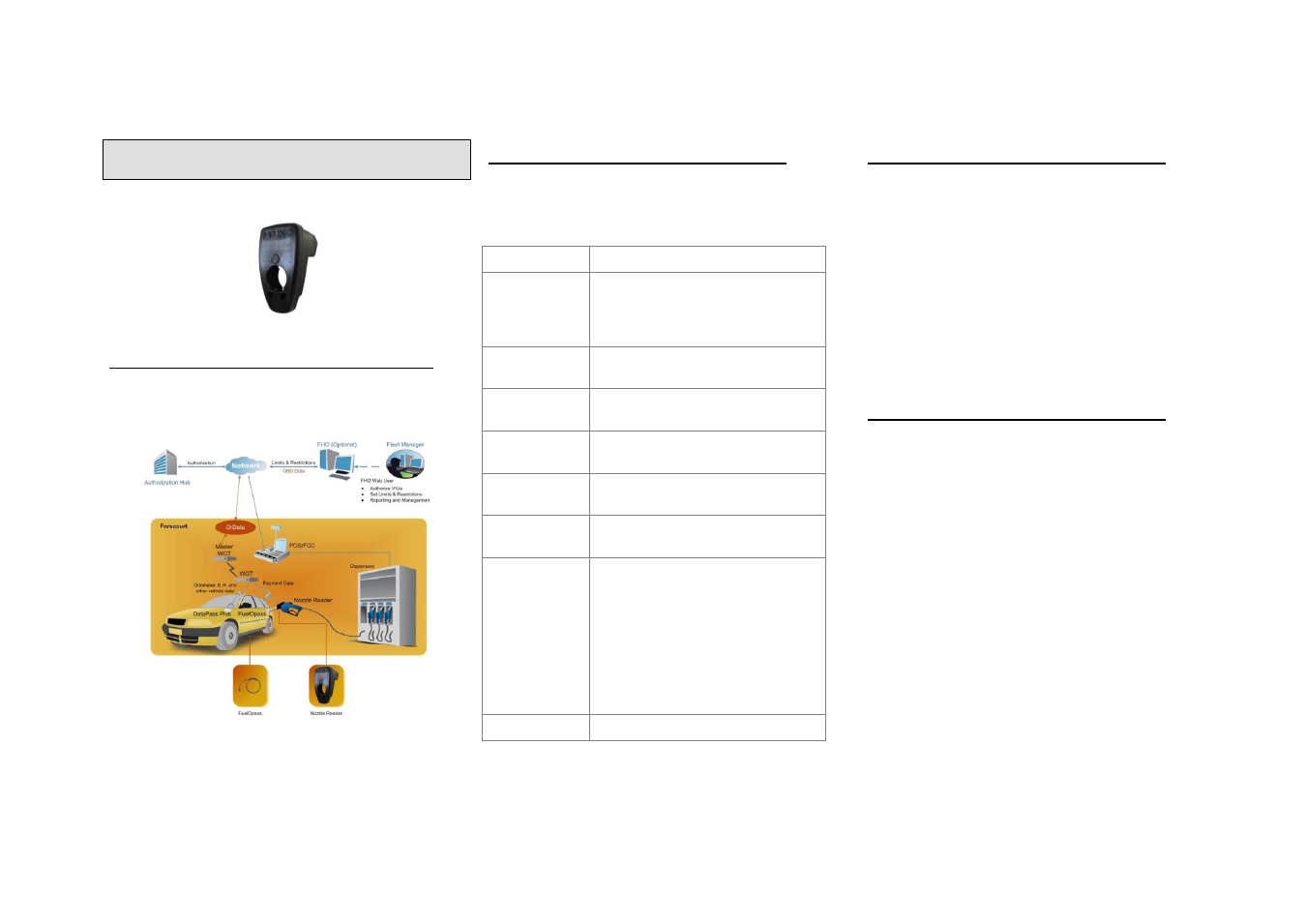
This manual describes the mechanical installation of
Gasboy's µWNR-F, part of the Fuel Point PLUS
Wireless Vehicle Identification System (see Figure 1).
Figure 1. Fuel Point PLUS System Architecture
2. SPECIFICATIONS
The following table lists the physical and electrical
specifications of the µWNR-F:
Table 1. µWNR-F Specifications
Parameter
Description
Supply
Voltage:
P/N 812539200 (x2)
Battery replacement should be
performed only by authorized service
personnel
Power
Consumption:
Active mode: 25mA typical. Standby
mode: 20µA
Battery Life
Span
2 to 3 years typical (typical activity:
~50 fuelling per day per nozzle)
Operating
Temperature:
-40
to +60
C
Storage
Temperature:
-40
to +60
C
Dimensions
(HxWxD):
µNR Assembly: 27.2x39.3x44.2mm
NR-F Housing: 106x56.9x72.2mm
Communication
Interface:
1. RF communication method to
WGT:
Frequency: 2.405-2.480 GHz
Typical transmission power:
3dbm (2mW)
2. RFID communication method
with FuelOpass:
Frequency: 119-135 kHz
Storage
1 year
3. REQUIRED TOOLS
The following tools are required to install and
service the µNR:
Flat screwdriver
Phillips screwdrivers
3mm and 2mm Allen keys
Utility knife
Loctite 243 medium strength threadlocker
glue, or similar
4. INSTALLATION KITS
Table 2 below lists the components included in the
different installation kits, specifically designed for
several fuelling nozzle models.
4.1. Nozzle Models
This document provides instructions for installing
the µWNR-F on the following nozzle models:
OPW 11AP/11BP
ZVA SL 1 /OPW DEF/ZVA SL 2 VR
Husky X
Husky 1A
TATSUNO
OPW 7H
ZVA 25