Standard configuration – Zilog EZ80F916 User Manual
Page 261
UM014423-0607
Using the Linker/Locator
ZiLOG Developer Studio II
eZ80Acclaim!
®
User Manual
241
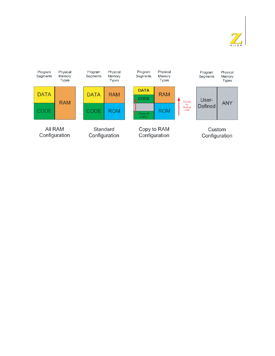
Figure 92. Linker Configurations
The preceding figure does not show the addresses for the beginning and end of physical
ROM and RAM. You can enter the address information on the Address Spaces page (see
“Project Settings—Address Spaces Page” on page 89). The linker configuration and
Address Spaces page information represent the hardware memory map.
As an example of what the linker command file does to support the linker configurations,
suppose your hardware only has RAM (the All RAM configuration). The linker therefore
must map logical ROM space to some part of physical RAM. In a 64K RAM configura-
tion, you might specify a RAM space of
0000h
–
FFFFh
. The linker command file contains
commands generated by ZDS II that group the ROM and RAM spaces together.
In most embedded applications, the logical ROM space resides in physical (hardware)
ROM, and the logical RAM space resides in physical RAM. For this (Standard) configura-
tion, the ROM and RAM memory spaces map directly to the corresponding ROM and
RAM hardware addresses. For example, in an architecture with a 24-bit addressing range,
you might have RAM at
C00000h
–
FFFFFFh
and ROM at
0h
–
00FFFFh
.
In the Copy to RAM configuration, the hardware has both ROM and RAM. However, per-
formance or operational considerations require that the code and data in physical ROM be
copied to a physical RAM address upon startup (to accommodate, for example, initialized
data that needs to be re-initialized when the board is reset). The Copy to RAM configura-
tion causes the startup code to copy some part of the ROM to a location in RAM.
Standard Configuration
In the Standard configuration, the hardware has both physical RAM and physical ROM.
The linker commands generated by ZDS II map logical RAM segments to physical RAM
and logical ROM segments to physical ROM. If the memory fields in the New Project