Zilog EZ80F916 User Manual
Page 136
UM014423-0607
Using the Integrated Development Environment
ZiLOG Developer Studio II
eZ80Acclaim!
®
User Manual
116
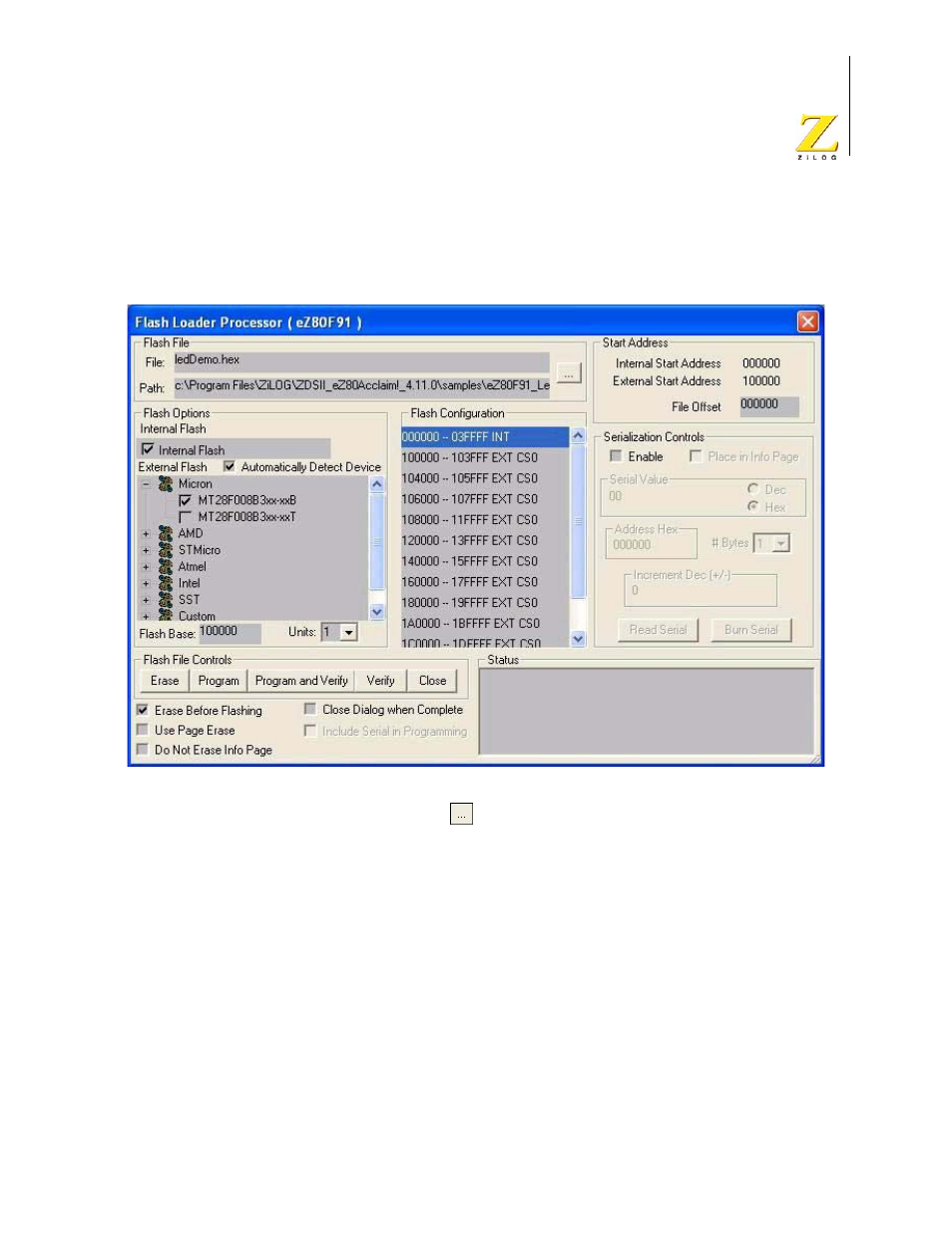
The Flash Loader connects to the target and sets up communication. The Flash Loader
Processor dialog box is displayed with the appropriate Flash target options for the
selected CPU.
Figure 78. Flash Loader Processor Dialog Box
4. Click on the Browse button (
) to navigate to the hex file to be flashed.
5. Select the Flash targets in the Flash Options area.
NOTE: The Flash Options displayed in the Flash Loader Processor dialog box depend on the CPU
you selected in the New Project dialog box (see “New Project” on page 39) or the General
page of the Project Settings dialog box (see “Project Settings—General Page” on page 57).
You must select at least one of the following check boxes in the Flash Options area
before erasing or flashing a target:
–
Internal Flash
The internal Flash memory configuration is defined in the
CpuFlashDevice.xml
file. The device is the currently selected microcontroller
or microprocessor. When the internal Flash is selected, the address range is
displayed in the Flash Configuration area with an INT extension.