Zilog EZ80F916 User Manual
Page 119
UM014423-0607
Using the Integrated Development Environment
ZiLOG Developer Studio II
eZ80Acclaim!
®
User Manual
99
ZDS assumes that the system clock change occurs somewhere after reset and before
the
main()
routine. For information about how to set up the charge pump current and
lock criteria, see the “Phase Locked Loop” chapter of the eZ80F91 MCU Product
Specification (PS0192).
NOTE: The clock frequency value is used even when the Simulator is selected as the
debug tool. The frequency is used when converting clock cycles to elapsed times in
seconds, which can be viewed in the Clock window when running the simulator.
See “Clock Window” on page 294.
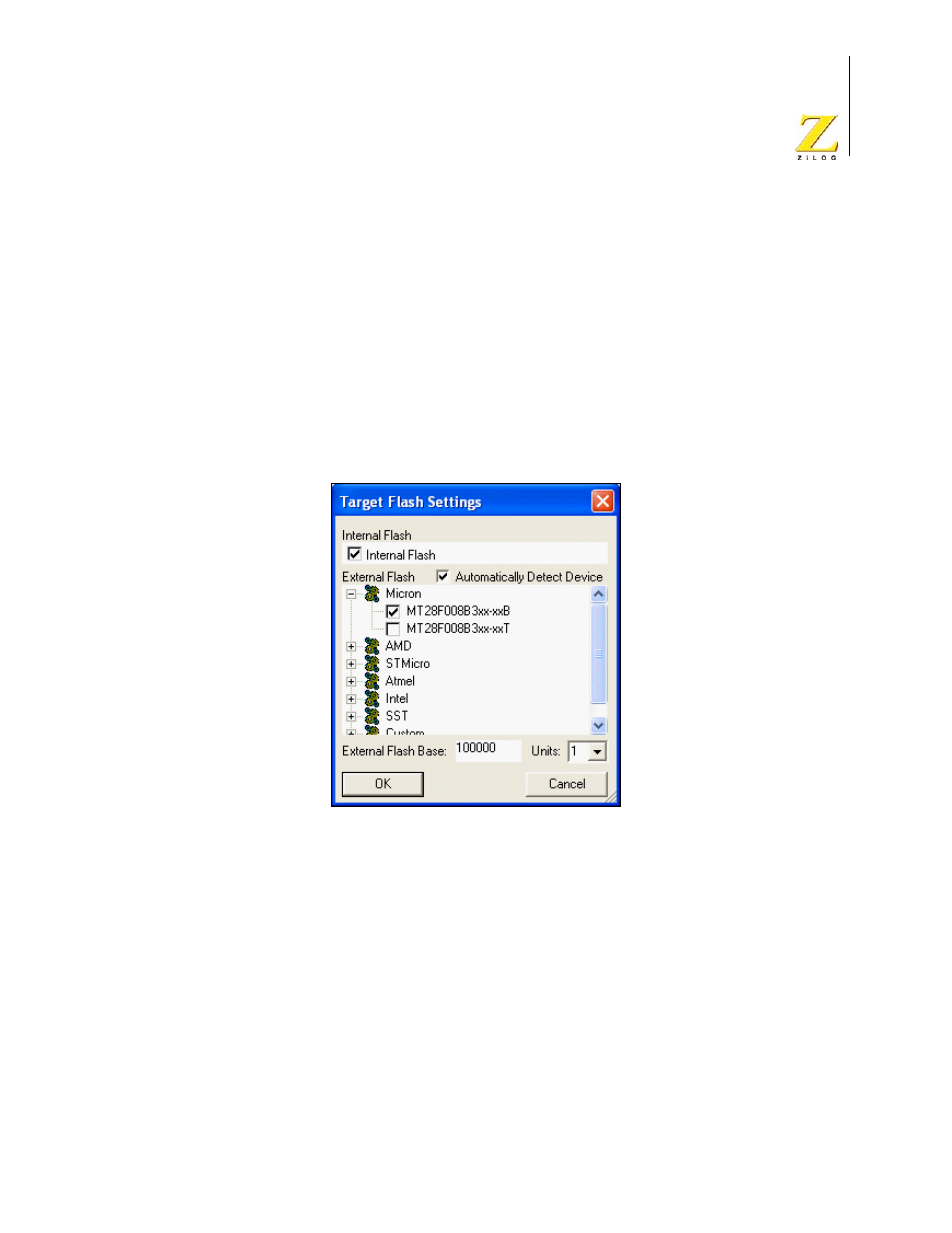
12. Click Configure Flash.
The Target Flash Settings dialog box is displayed.
Figure 65. Target Flash Settings Dialog Box
–
Select the Internal Flash check box if you want to use internal Flash.
The internal Flash memory configuration is defined in the
CpuFlashDevice.xml
file. The device is the currently selected microcontroller
or microprocessor.
–
If you want to use external Flash, select the Automatically Detect Device check
box or select which Flash devices you want to program.
The Flash devices are defined in the
FlashDevice.xml
file.
The device is the current external Flash device’s memory arrangement. The
external Flash device options are predefined Flash memory arrangements for
specific Flash devices such as the Micron MT28F008B3. The Flash Loader uses
the external Flash device option arrangements as a guide for erasing and loading
data to the appropriate blocks of Flash memory.