Figure a-4 – Digilent 6003-410-000P-KIT User Manual
Page 74
74
XUP Virtex-II Pro Development System
1-800-255-7778
UG069 (v1.0) March 8, 2005
Appendix A: Configuring the FPGA from the Embedded USB Configuration Port
R
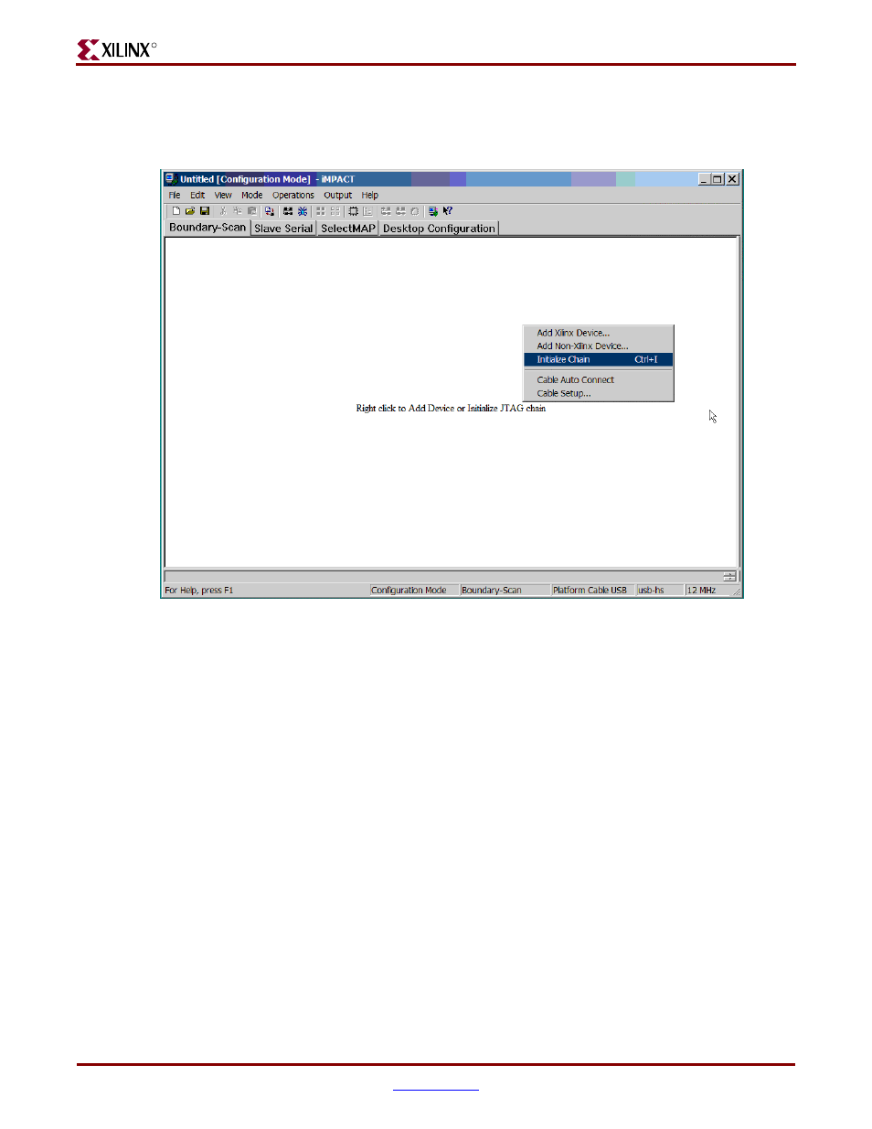
After the programming cable type and speed has been selected, the JTAG chain must be
defined. Right click in the iMPACT window and select “Initialize Chain” from the drop-
down menu shown in
.
A status bar on the bottom edge of the iMPACT GUI provides useful information about the
operating conditions of the software and the attached cable. If the host port is USB 1.1,
Platform Cable USB connects at full-speed, and the status bar shows “usb-fs.” If the host
port is USB 2.0, Platform Cable USB connects at high-speed and the status bar shows “usb-
hs.” The active JTAG TCK speed is shown in the right-hand corner of the status bar.
, shows a Platform Cable USB connected at high-speed, using a Boundary-Scan
Configuration Mode with a JTAG TCK of 12 MHz.
If there are no configurable expansion boards attached to the basic system, the Initialize
Chain command should identify three devices in the chain: the Platform FLASH PROM
(XCF32P), followed by the System ACE controller (XCCACE), and followed by the FPGA
(XC2VP30). Any programmable devices on expansion boards follow the FPGA in the
configuration chain. A properly identified JTAG configuration chain for the basic system is
shown in
Figure A-4:
Initializing the JTAG Chain