Mgt serial ata test, Additional hardware required, Figure d-2 – Digilent 6003-410-000P-KIT User Manual
Page 102
102
XUP Virtex-II Pro Development System
1-800-255-7778
UG069 (v1.0) March 8, 2005
Appendix D: Using the Golden FPGA Configuration for System Self-Test
R
Additional Hardware Required
•
9-pin male-to-female straight-through serial communications (RS-232) cable
•
PC running Hyper Terminal or similar terminal program set to 9600 baud, 8-bit data,
no parity, 1 stop bit, and no flow control.
For a free PC terminal program, see:
MGT Serial ATA Test
This test verifies proper operation of the three SATA Multi-Gigabit Transceivers (MGTs).
This is accomplished using a modified version of the Xilinx Aurora 201 demo design,
which can be found at:
This test version uses the Aurora protocol to exercise the high-speed serial interfaces of the
XUP Pro board at 1.5 Gb/s with 8B/10B encoding. For simplicity and cost reduction, the
test is designed to use a standard 1.5 Gb/s serial ATA cable available from most computer
supply stores. This test was verified using both 1.0-meter and 0.5-meter cables.
The basic procedure uses a cable to loop back bidirectional data from one of the two host
transceivers to the target transceiver of the same board. To test the second pair, the serial
ATA cable must be manually moved to the other host connector and the same test is rerun
monitoring the other host, which is selected via the test program software.
Note:
It is good practice to turn off power to the board before and while switching the SERIAL
ATA cable.
However, the MGTs are in a powered down mode while not displaying test status. It is
important to note that some additional MGT functionality is controllable once the test is
started. The test operation can be modified and interrupted from the test status report
menu. Either one or both of the two MGTs being exercised in the test can be switched to a
serial or parallel INTERNAL loopback mode. The internal serial loopback mode is useful
in diagnosing if the MGT is shorted on the PCB. With the internal serial loopback enabled,
a properly terminated MGT is able to transmit to itself and receive correct data.
Additional Hardware Required
•
9-pin male-to-female straight-through serial communications (RS-232) cable
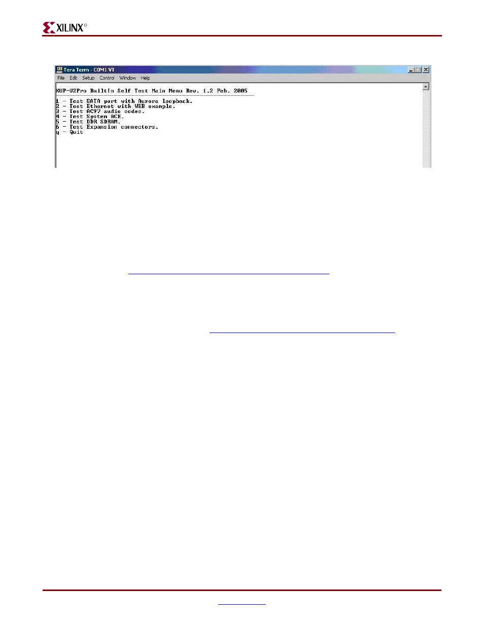
Figure D-2:
Built-In Self-Test Main Menu
ug069 01a 021005