Digilent 410-145P User Manual
Digilent Hardware
C
C
e
e
r
r
e
e
b
b
o
o
t
t
N
N
a
a
n
n
o
o
™
™
R
R
e
e
f
f
e
e
r
r
e
e
n
n
c
c
e
e
M
M
a
a
n
n
u
u
a
a
l
l
®
w w w . d ig i l en t inc . c om
Revision: February 6, 2009
Note: This document applies to REV A of the board.
215 E Main Suite D | Pullman, WA 99163
(509) 334 6306 Voice and Fax
Doc: 502-095
page 1 of 6
Copyright Digilent, Inc. All rights reserved. Other product and company names mentioned may be trademarks of their respective owners.
Overview
The Cerebot Nano is the smallest in the
Cerebot line of boards offered by Digilent. The
board’s small size allows it to be used as either
a peripheral that can be plugged directly into
other Digilent boards or as a tiny stand-alone
embedded control board. In spite of its small
size, the Cerebot Nano is packed with
features.
The Cerebot Nano’s versatile design and
programmable microcontroller allows you to
control different external devices and program
the board for multiple uses. The board has
many I/O connectors and supports a number of
programming tools including Atmel AVR
Studio
®
4 and WinAVR.
The Cerebot Nano has a number of
connections for peripheral devices. Digilent
peripheral modules (Pmods™) include H-
bridges, analog-to-digital and digital-to-analog
converters, a speaker, switches, buttons,
LEDs, RS232 converters, screw terminal
connectors, BNC connectors, servo motors,
and more. For more information see
www.digilentinc.com
.
Features include:
•
ATmega168 microcontroller
•
one 6-pin and two 12-pin connectors for
Digilent Pmod peripheral module
boards
•
up to eight analog-to-digital (ADC) input
channels
•
four LEDs
•
ESD protection for all I/O pins
•
in-system programming support using
the Digilent parallel JTAG cable or the
Digilent USB JTAG/SPI cable.
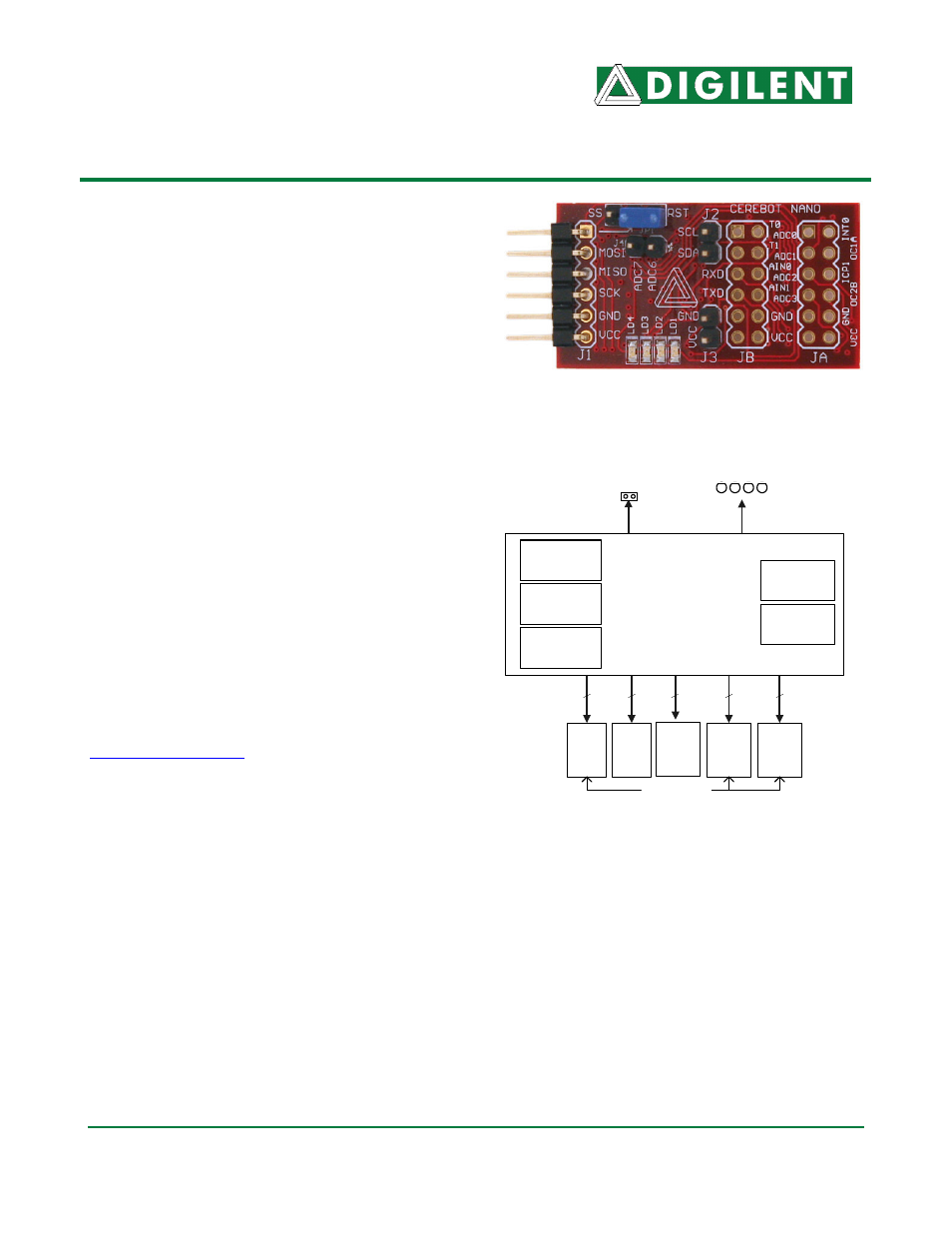
ATMega168
MLF32
JA
ADCs/
IO
16K Flash
(Internal)
4 LEDs
12
512 EEPROM
(Internal)
Internal
Oscillator
UART, SPI,
& TWI ports
J4
ADC6/7
J1
SPI/
ISP
12
2
6
1K SRAM
(Internal)
Cerebot Nano
TM
Power
connector
J2/
TWI
2
JB
TWI/
USART/
IO
I/O Connectors
Cerebot Nano Circuit Diagram