Using the serial ports, Figure 2-16 – Digilent 6003-410-000P-KIT User Manual
Page 60
60
XUP Virtex-II Pro Development System
UG069 (v1.0) March 8, 2005
Chapter 2: Using the System
R
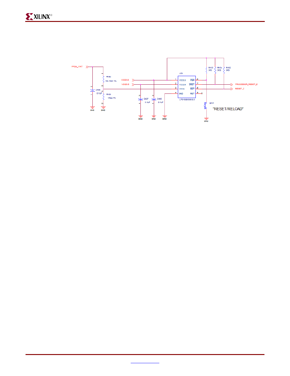
processor reset pulse of 100 microseconds is applied to the PROCESSOR_RESET_Z signal.
The RESET_RELOAD circuit is shown in
.
Using the Serial Ports
Serial ports are useful as simple, low-speed interfaces. These ports can provide
communication between a Host machine and a Peripheral machine, or Host-to-Host
communications. The XUP Virtex-II Pro Development System provides two different types
of serial ports, a single RS-232 port and two PS/2 ports.
The RS-232 standard specifies output voltage levels between -5V to -15V for a logical 1, and
+5V to +15V for a logical 0. Inputs must be compatible with voltages in the range -3V to -
15V for a logical 1 and +3V to +15V for a logical 0. This ensures that data is correctly read
even at the maximum cable length of 50 feet. These signaling levels are outside the range of
voltages that can be supported by the Virtex-II Pro family of FPGAs, requiring the use of a
transceiver. The connector is a DCE-style that allows the use of a straight-through 9-pin
serial cable to connect to the DTE-style serial port connector available on most personal
computers and workstations. A null-modem cable is not required.
shows the
implementation of the serial port used on the XUP Virtex-II Pro Development System.
The MAX3388E is a 2.5V powered device that operates as a transceiver to shift the
signaling levels from the voltages supported by the FPGA to those required by the RS-232
specification. The MAX3388E has two receivers and three transmitters and is capable of
running at data rates up to 460 kb/s while maintaining RS-232-compliant output levels.
There are five signals from the FPGA to the RS-232 serial port: RS232_TX_DATA,
RS232_DSR_OUT, RS232_CTS_OUT, RS232_RX_DATA, and RS232_RTS_IN. The Transmit
Data and Receive Data provide bidirectional data transmission, while Request To Send,
Clear To Send, and Data Set Ready provide for hardware flow control across the serial link.
identifies the RS-232 signal connections to the FPGA.
IBM developed the PS/2 ports for peripherals as an alternative to serial ports and
dedicated keyboard ports. These ports have become standard connectors on PCs for
connecting both keyboards and mice. They use a 6-pin mini-DIN connector and a
bidirectional synchronous serial interface, with a bidirectional data signal and a
unidirectional clock. The XUP Virtex-II Pro Development System provides two PS/2 ports,
for keyboard and mouse attachment. The PC mouse and keyboard use the two-wire RS/2
serial bus to communicate with the host FPGA. The PS/2 bus includes both clock and data
with identical signal timings and both user 11-bit data words that include a start bit, stop
Figure 2-16:
RELOAD and CPU RESET Circuit
ug069_16_021505