Digilent 6032-410-000P-BOARD User Manual
Digilent Hardware
O
O
r
r
b
b
i
i
t
t
B
B
o
o
o
o
s
s
t
t
e
e
r
r
P
P
a
a
c
c
k
k
™
™
R
R
e
e
f
f
e
e
r
r
e
e
n
n
c
c
e
e
M
M
a
a
n
n
u
u
a
a
l
l
Revision: June 5, 2013
Note: This document applies to REV A of the board.
1300 NE Henley Court, Suite 3
Pullman, WA 99163
(509) 334 6306 Voice | (509) 334 6300 Fax
Doc: 6032-502-000
page 1 of 4
Copyright Digilent, Inc. All rights reserved. Other product and company names mentioned may be trademarks of their respective owners.
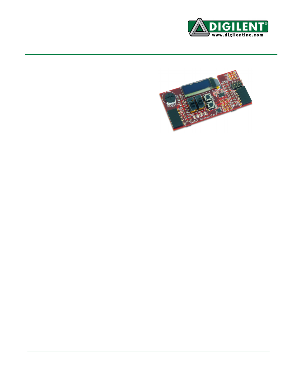
Overview
The Digilent Orbit BoosterPack™ is an
add-on board for the Texas Instruments
Stellaris® LaunchPad microcontroller
evaluation kit. The Orbit greatly expands
the input/output capabilities of the
LaunchPad, as well as introducing Digilent
Pmod™ expansion connectors.
Features Include:
•
two 1x6 Digilent Pmod™
connectors
•
3-axis accelerometer
•
256 Kbit I
2
C EEPROM
•
I
2
C temperature sensor
•
128x32 pixel OLED display
•
analog potentiometer
Orbit BoosterPack Hardware
Description
Introduction
The following gives a basic description of the
input/output hardware contained in the Orbit
BoosterPack and how to use it. Refer to
Appendix A for a table showing pin definitions.
OLED Graphic Display
The Orbit board provides a 128x32 pixel,
organic LED (OLED), graphic display panel.
The graphic display panel used is the
WiseChip/Univision UG-23832HSWEG04. This
display uses the Soloman Systech SSD1306
display controller.
The UG2832 has a power on/power off
sequence that should be followed. Failure to
follow the power on/power off sequence can
shorten the life of the display. The Orbit
provides two FETs for software control of the
two power supplies for the display. The
VDD_OLED control is used to turn on/off the
power to the logic of the display. The
VBAT_OLED control is used to turn on/off
power to the OLED display itself. These two
pins have pull-up resistors to turn off their
respective power supplies when not being
driven. The pins are made to be outputs and
are driven low to turn on the power supplies.
Power on sequence:
Apply power to VDD
Send Display Off command
Initialize display to desired operating mode
Clear screen
Apply power to VBAT
Delay 100ms
Send Display On command
Power off sequence:
Send Display Off command
Power off VBAT
Delay 100ms
Power off VDD
The display has a D/C pin (display or
command select) that is used to determine
whether bytes sent to the display are
interpreted as commands or as display data.
The D/C pin is driven high for display buffer
access and is driven low for command access.
This pin is shared with VBUS detection on the
LaunchPad. If VBUS is present, the pull-down
resistor acts as a pull-up resistor in conjunction