3 circulator wiring – AERCO Esteem Boiler with EZ-Set Controller User Manual
Page 56
GF-135 Esteem 399 Low NOx Boiler
Chapter 9
OMM-0089_0A
Installation, Operation & Maintenance Manual External Wiring
9.3 CIRCULATOR WIRING
To wire the circulator, perform the following.
Wiring the Circulator
1. Reference Table 9-1 to determine the appropriate circulator connections required. The
circulator connections used will depend on the systems piping layout.
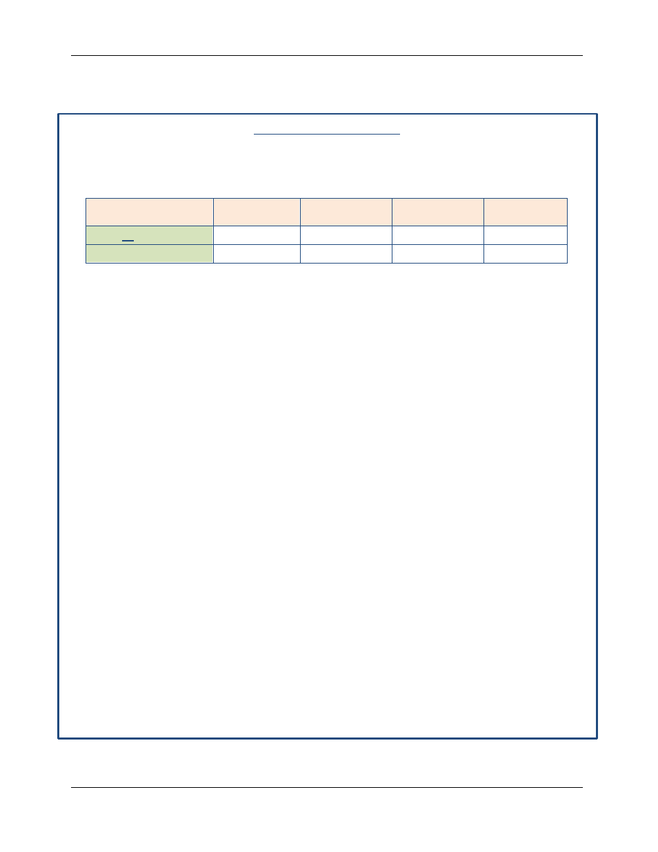
Table 9-1: Circular Operation Default Settings
Call
CH (1) Pump
DHW Pump
Auxiliary
Boiler Pump
System
Pump
CH 1 or CH 2 Call
ON
OFF (Note 1)
ON
ON
DHW Call
OFF (Note 1)
ON
ON
OFF (Note 1)
NOTE 1
Domestic Hot Water Priority can be disabled in the Installer Menu
which allows the CH (1) and DHW circulators to operate at the
same time. Consult Chapter 10, Basic Esteem Controls, for more
information.
NOTES
•
The system circulator can also been enabled during a DHW Call
in the Installer Menu. Consult Section 10, Basic Esteem
Controls, for more information.
•
Each circulator is individually fused with a 2.5A fuse located in
the terminal strip. The total combined amp draw of the CH (1),
DHW, and Auxiliary Boiler Circulators must not exceed 3 amps at
any time for the Esteem boiler. Use an isolation relay to lower the
total combined amp draw if exceeding these limits.
2. Connect the CH circulator to the line voltage terminal strip on the wiring panel below the
Esteem control module, as shown in Figure 8-3. The CH circulator is enabled during a CH 1
or CH 2 call. This circulator is used to supply heat to the central/space heating loop.
3. Connect the DHW circulator to the line voltage terminal strip on the wiring panel below the
Esteem control module, as shown in Figure 8-3. The DHW circulator is enabled during a
DHW call. This circulator is used to supply heat to an indirect hot water heater.
4. Connect the Auxiliary Boiler circulator to the line voltage terminal strip on the wiring panel
below the Esteem control module, as shown in Figure 8-3. The auxiliary boiler circulator is
enabled during a CH or a DHW call. This circulator is typically used in retrofit applications
where the CH and DHW systems are connected to a common boiler supply.
5. Connect the System circulator to the line voltage terminal strip on the wiring panel below the
Esteem control module, as shown in Figure 8-3 The system circulator is enabled during a
CH1 or CH2 call with the factory default settings. This circulator is typically used to circulate
water in the secondary CH loop when zoning with zone valves.
Page 56 of 188
AERCO International, Inc. • 100 Oritani Dr. • Blauvelt, NY 10913
OMM-0089_0A
MC1 06/19/14
Ph.: 800-526-0288