Chapter 8: internal wiring, 1 general requirements, 2 fuse locations – AERCO Esteem Boiler with EZ-Set Controller User Manual
Page 51: 1 ez-setup controller module fuses location, Chapter 8, Internal wiring
GF-135 Esteem 399 Low NOx Boiler
Chapter 8
OMM-0089_0A
Installation, Operation & Maintenance Manual Internal Wiring
CHAPTER 8: INTERNAL WIRING
WARNING!
ELECTRICAL SHOCK HAZARD.
For your safety, disconnect
electrical power supply to the unit before servicing or making any
electrical connections to avoid possible electric shock hazard.
Failure to do so can cause severe personal injury or death.
WARNING!
Prior to servicing, label all wires before disconnecting. Wiring errors
can cause improper and dangerous operation. Verify proper wiring
and operation after servicing.
8.1 GENERAL REQUIREMENTS
•
Wiring must be NEC Class 1.
•
If original wiring as supplied with the unit must be replaced, use only Type T 90ºC wire
or equivalent as a minimum.
•
The Esteem boiler must be electrically grounded as required by National Electrical Code
ANSI/NFPA 70—latest edition and / or the Canadian Electrical Code Part 1, CSA C22.1,
Electrical Code.
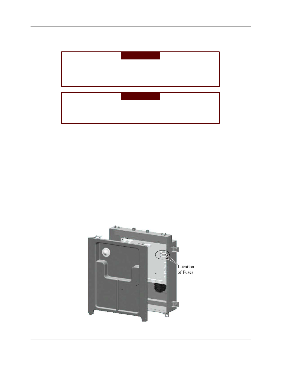
8.2 FUSE LOCATIONS
8.2.1 EZ-SETUP Controller Module Fuses Location
The control module contains two (2) internal replaceable 5A fuses, as shown in Figure 8-1.
Figure 8-1: Control Module Fuse Location
Page 51 of 188
AERCO International, Inc. • 100 Oritani Dr. • Blauvelt, NY 10913
OMM-0089_0A
MC1 06/19/14
Ph.: 800-526-0288