Prepare meter sense ports, Connect meter sense lines, 147), are – Great Plains YP625PD Predelivery Manual User Manual
Page 78
74
Great Plains Manufacturing, Inc.
YP625PD/TD/925TD
401-754Q
07/05/2011
Prepare Meter Sense Ports
Refer to Figure 147, Figure 148 and Figure 149
Sense lines are connected from the chamber
to
5 or 6 meters. Sensing rows are:
329. Inspect the left side of all row units.
If all meters at the correct rows already have
adaptor
fittings installed at their sense ports
,
continue at “Connect Meter Sense Lines”.
If incorrect rows have adaptors, exchange the adap-
tors with plugs
at the correct rows, and con-
tinue at “Connect Meter Sense Lines”. See
step 330 to step 332 for exchange instructions.
If no rows have adaptors
, continue at step 330.
330. At each Sensing Row from the table above, where
an adaptor
is to be installed, remove:
817-829C PLUG, FLUSH HEAD POLYETH 7/16
This plug is located at
, above the drive sprocket,
in between the air and seed elbows. Remove the
meter rain cover, and any seed disc present. Use a
small blunt punch to push the plug out from the
sprocket side. Unless needed where an adaptor is
removed, this plug is not re-used.
331. At each incorrect row, where an adaptor is installed,
remove and save one set:
803-374C NUT HEX JAM 7/16-20 PLT
891-122C AD 7/16MORB X 1/4HB BRASS
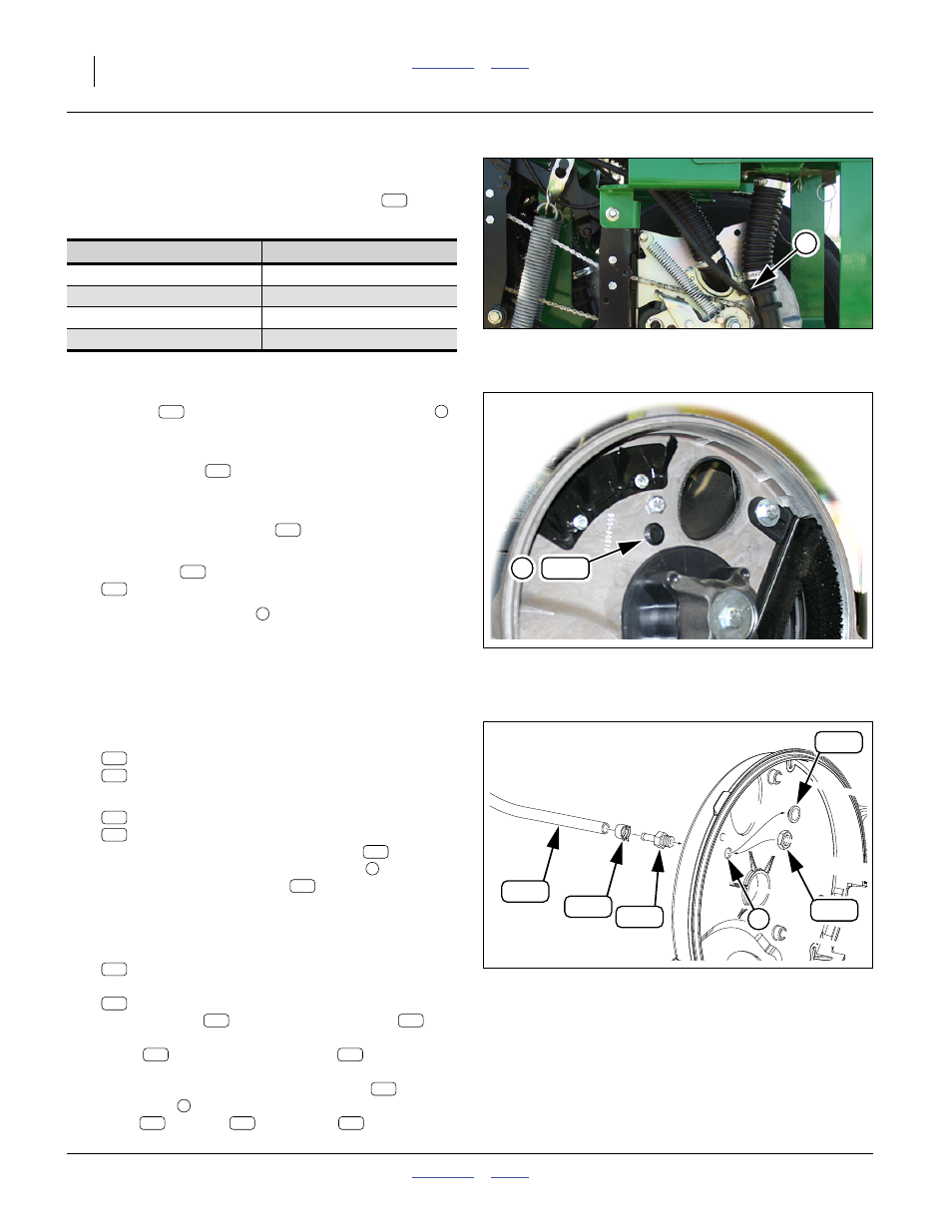
332. At each sense line row, select one set:
803-374C NUT HEX JAM 7/16-20 PLT
891-122C AD 7/16MORB X 1/4HB BRASS
Insert the threaded end of the adaptor
, from the
sprocket side, through the sense port
of the
meter. Secure with jam nut
.
Connect Meter Sense Lines
Refer to Figure 146 on page 73, and Figure 149
333. Select two:
800-395C CLAMP SPRING BAND 1/2 OD HOSE
and the coil of:
990-021R HOSE 1/4 RUBBER AIR
Place a clamp
on one end of the hose
.
Connect that end to the top available adaptor
fitting
on the sensor chamber
. Route the
hose along the air manifold, and then along the
supply air hose at the row, to the fitting
at the
meter port
. Cut the hose to length. Secure
hose
to fitting
with clamp
.
Planter Model
Sensing Rows
2, 3, 5, 6, 8, 9
1, 2, 3, 4, 5, 6
1, 2, 3, 4, 5
Null4:
Figure 147
Meter Sensor Port
Q0088
3
186
Null4: .
Figure 148
Meter Sensing Port Plug
Q0094
372
3
401
3
372
401
401
372
3
Null4: .
Figure 149
Meter Sensing Port Connected
Q0095
372
305
401
250
403
3
305
401
305
401
401
3
305
250
403
250
403
383
186
401
3
403
401
250