Hopper identification, Install left hopper, Hopper identification install left hopper – Great Plains YP625PD Predelivery Manual User Manual
Page 54: Step 219
50
Great Plains Manufacturing, Inc.
YP625PD/TD/925TD
401-754Q
07/05/2011
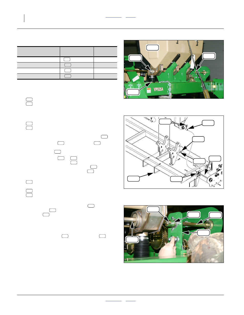
Hopper Identification
Install Left Hopper
214. Select one of (per table above):
407-560L 4-OUTLET DRY FERT HOPPER ASSY
407-561L 3-OUTLET DRY FERT HOPPER ASSY
Select an unmodified hopper. Attach hoist lines.
Refer to Figure 101, Figure 102 and Figure 103
215. Select one set:
407-073D COUPLER, DRY FERT
805-065C PIN WIRE RETAINING 1/4 X 1 3/4
These may be located on the left end of the hopper
shaft, or right end of the fertilizer jackshaft
.
216. Place the coupler
on the jackshaft
, with the
pin hole closer to the right end of the coupler.
Secure with pin
using the hole in the left shaft.
217. Hoist the hopper (
or
) to the front tool bar,
with the meter drop lines
behind the tool bar.
Bring the left end of the hopper shaft
nearly into
contact with the installed jackshaft
.
218. Select two:
806-052C U-BOLT 5/8-11 X 7 1/32 X 8 1/2
and four sets:
804-022C WASHER LOCK SPRING 5/8 PLT
803-021C NUT HEX 5/8-11 PLT
Loosely secure the hopper assembly to the tool bar.
219. Adjust the jackshaft mount bracket
to bring the
hopper shaft
into alignment with the
jackshaft
.
220. Adjust the hopper position on the tool bar for a
shaft-to-shaft gap of:
5 mm (
3
⁄
16
in).
221. Engage the coupler
. Secure with pin
.
Planter
Model
Hopper
Assemblies
Coupler
Shafts
407-560L
a
a. Center hopper modified per step 209 - step 213 on page 49.
407-661D
407-560L
407-661D
407-560L
407-661D
407-561L
407-659D
Null4:
Figure 101
Position Hopper
Q0070
229
233
362
217
216
216
216
217
216
217
Null4:
Figure 102
Hopper Installation Hardware
31882
313
325
208
287
339
229
227
208
325
229
208
229
325
216
217
362
233
229
339
313
287
Null4:
Figure 103
Align Shafts
Q0072
208
325
229
227
233
227
233
229
208
325