Install fan mast – Great Plains YP625PD Predelivery Manual User Manual
Page 45
Great Plains Manufacturing, Inc.
Planter Assembly
41
07/05/2011
401-754Q
Refer to Figure 83
174. With the manifold
facing front, and the
supporting tube
on top, rest the main pipe on
the air pipe supports
.
Align the center of the open end of the inlet tee
at 10.2 cm (4.0 in) left of implement center-line.
Adjust the position of the air pipe supports
as
necessary to avoid interference between parts.
Rotate the manifold so that the outlets
point
straight down.
Tighten fasteners at lower U-bolts and clamps.
Null4:
Install Fan Mast
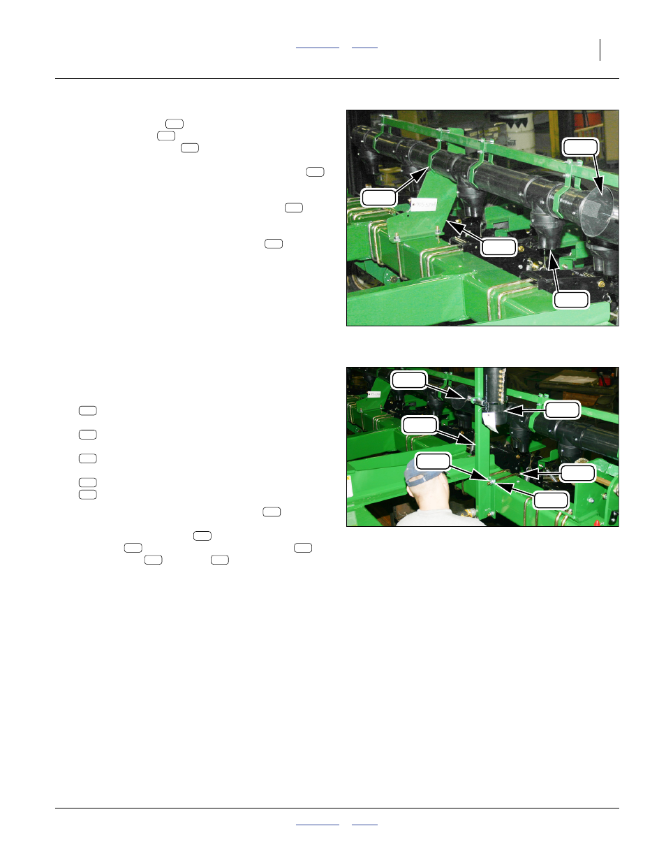
Refer to Figure 84
175. Select one:
401-656H FAN MOUNT WELDMENT
This typically has pre-installed on it:
403-361S SENSOR CHAMBER ASY
two:
806-052C U-BOLT 5/8-11 X 7 1/32 X 8 1/2
and four sets:
804-022C WASHER LOCK SPRING 5/8 PLT
803-021C NUT HEX 5/8-11 PLT
176. Install the mast (fan mount weldment)
on the
front face of the rear tool bar. Position it just to the
left of the manifold inlet
. Face the sensor
chamber
to the left. Secure with U-bolts
,
lock washers
and nuts
.
Null4:
Figure 83
Install Manifold
Q0065
369
197
200
371
196
194
200
369
200
371
Null4:
Figure 84
Install Fan Mast
Q0061
151
186
287
313
268
369
151
186
339
313
287
151
369
186
339
313
287