Release gauge wheel arms, Release front tool bar, Release gauge wheel arms release front tool bar – Great Plains YP625PD Predelivery Manual User Manual
Page 18: Ms (figure 19), Ue at step 15 on
14
Great Plains Manufacturing, Inc.
YP625PD/TD/925TD
401-754Q
07/05/2011
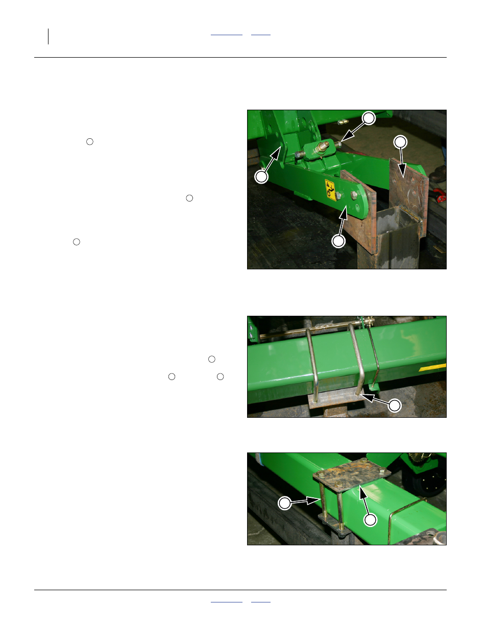
Release Gauge Wheel Arms
Refer to Figure 19 (which depicts a 2-point or 3-point type
gauge wheel, with disconnected spring adjuster)
If the gauge wheel arms are not secured to the rack,
continue at step 17.
15. Remove all (one to six) sets of nuts, lock washers
and bolts
that secure gauge wheel arms to the
rack. These fasteners are not re-used.
16. If the gauge wheel arm spring adjuster is
disconnected, as shown at right, re-connect it at this
time.
Remove and save the bolt and sleeve
from each
side of the spring adjuster block.
Push the arm down at the rack connection, to align
the spring adjuster block with the lower set of
holes
at the mount weldment.
Re-insert and secure the bolts and sleeves.
Note: If the spring adjuster was not disconnected, but is
in the upper weldment holes, leave it as is. This
shipping configuration is changed to field
configuration at step 67 on page 24.
Null4:
Release Front Tool Bar
Refer to Figure 20 or Figure 21
If the front tool bar is not secured to the rack, continue at
step 18.
17. Remove any nuts, lock washers and U-bolts
that
secure the front tool bar to the rack. Remove any
nuts, lock washers, straight bolts
and plates
that secure the front tool bar to the rack. These
fasteners are not re-used.
anchor-only
Null4:
Null4:
Figure 19
Gauge Wheel Arm Bolted to Rack
Q0014
3
4
5
Null4:
Figure 20
Tool Bar U-Bolted to Rack
Q0015
6
7
8
Null4:
Figure 21
Tool Bar Plate-Bolted to Rack
Q0016
7
8