Support the main frame, Secure drive shaft, Rack section closeout – Great Plains YP625PD Predelivery Manual User Manual
Page 19: Step 20, Step 18
Great Plains Manufacturing, Inc.
Rack Unloading
15
07/05/2011
401-754Q
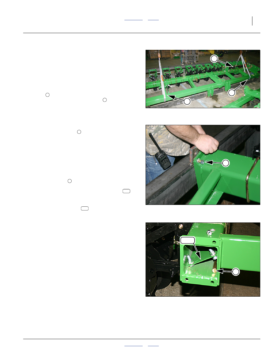
Support the Main Frame
When completely released (after step 20), the mainframe
is lifted out of the rack frame.
Refer to Figure 22
18. Unless lines are still connected to the planter main
frame from step 8 on page 12. Connect lines to
support the weight prior to releasing the final bolts.
Loop around the front tool bar inside the end
tubes
and just outboard of the ribs. Loop around
the outer gauge wheel weldments
Refer to Figure 23
19. Use the hoist to lift the planter main frame just until
the tool bar end bolts
are loose.
20. Remove the nuts, lock washers and bolts. They are
not re-used.
21. Hoist the planter main frame clear of the rack. Keep
it level during movement. Set it on the ground near
its staging area for further assembly.
Secure Drive Shaft
Refer to Figure 24
The meter drive shaft
is partially assembled, with all
final driving “DRIVING” sprockets, and shipped inside the
rear planter main frame tool bar. The frame caps
,
and their fasteners, are also in the tube.
22. If there is any concern about the shaft getting lost,
remove the frame caps
and loosely secure the
caps to the end of the tool bar tubes.
Null4:
Rack Section Closeout
23. If the rack is the bottom rack (with the floor), inspect
it for additional parts not removed at step 4. Save
any parts found. Dispose of rack.
Repeat step 57 through step 23 for the remaining rack
sections.
Null4:
Null4:
Figure 22
Planter Hoist Points
Q0011
1
2
2
Null4:
Figure 23
Planter Frame End Bolts
Q0017
3
3
4
145
145
Null4:
Figure 24
Shaft and Cap Inside Tube
Q0024
4
145