Install fan hydraulic hoses, Assemble fan hoses, Install fan hoses – Great Plains YP625PD Predelivery Manual User Manual
Page 47: Rp a
Great Plains Manufacturing, Inc.
Planter Assembly
43
07/05/2011
401-754Q
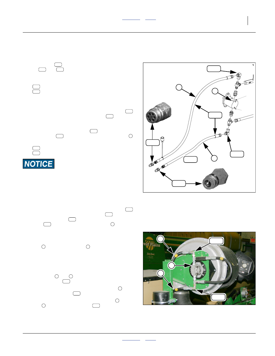
Install Fan Hydraulic Hoses
Assemble Fan Hoses
Refer to Figure 87
If the fan hoses
already have quick-disconnect (QD)
fittings (
and
) attached, continue at “Install Fan
180. Select one each:
811-394C CP 3/4FORB MALE QD POPPET TYPE
841-481C HH1/2R2 230 3/4FJIC 3/4MORB
Note: The tractor(s) to be used may require a different
style of quick-disconnect fitting.
181. Remove any protective plug from the QD fitting
,
and from the MORB end of the hose
. Retain
any tethered cap for field use.
Attach the QD coupler fitting
to the MORB end
of the hose
. This hose is the pressure hose
182. Select one each:
841-529C CP 3/4FORB MALE QD RELIEF
841-481C HH1/2R2 230 3/4FJIC 3/4MORB
Equipment Damage Risk:
If the tractor(s) to be used require a different style of
quick-disconnect fitting, be sure to use a relief coupler or
low-seep coupler. If the fan return line is completely sealed by
a poppet or check valve fitting, fan seals could be damaged.
Normal temperature changes can cause damaging oil pressure
changes in a completely sealed fan hydraulic system.
183. Remove any protective plug from the QD fitting
,
and from the MORB end of the hose
.Attach the
QD coupler fitting
to the MORB end of the
hose
. This hose is the return hose
Install Fan Hoses
If the hoses were pre-assembled, examine the hoses,
and the instructions above, to identify which is
pressure
and which is return
Note: If the QD fittings must be replaced due to tractor
requirements, see the instructions and Notice
above.
184. Remove any protective plugs from the FJIC ends of
the hoses (
and
) and any protective caps on
the fan elbows
.
185. Connect the FJIC end of the pressure hose
to the
bottom (inlet) elbow
at the hydraulic fan.
186. Connect the FJIC end of the return hose
port
, the top (return) elbow
at the hydraulic
fan.
Null4:
Null4:
Figure 87
Fan Hoses
31754
A Port
B Port
354
390
389
389
352
352
R
P
A
389
354
390
354
389
354
389
354
389
390
389
390
389
390
389
R
Null4:
Figure 88
Fan Hydraulics
31869
352
352
352
352
R
352